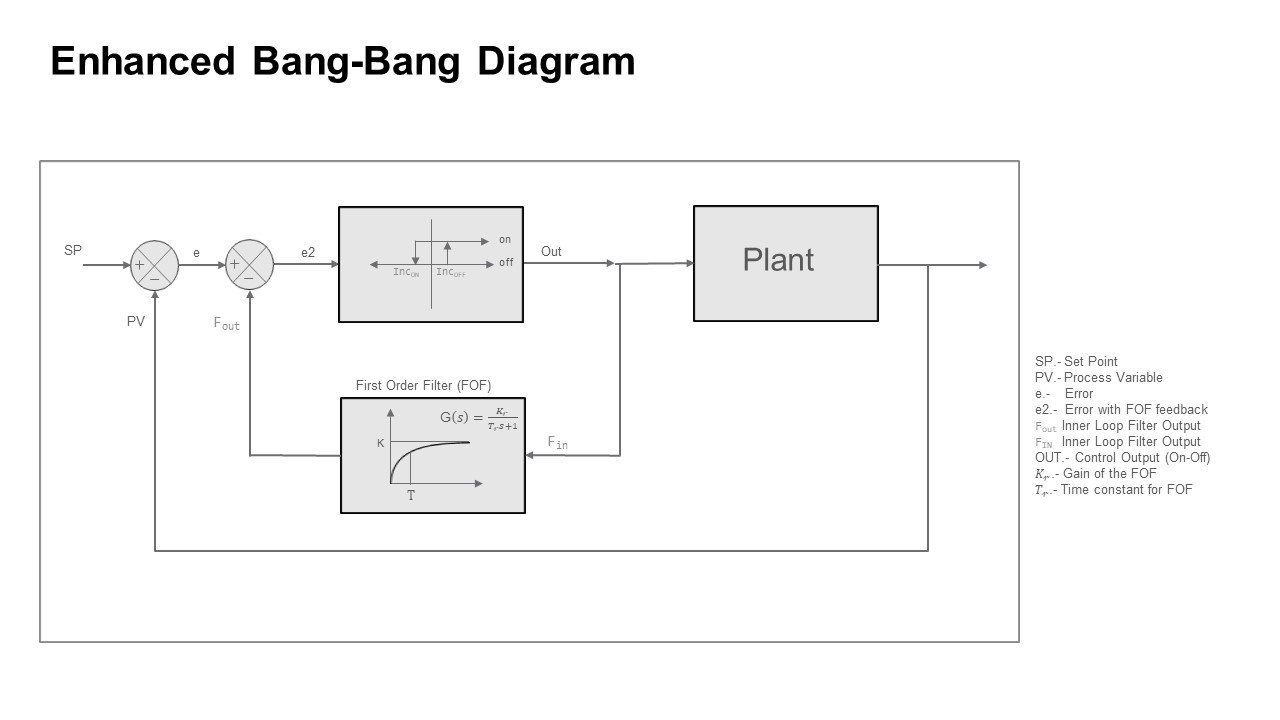
The bang-bang principle of operation is the on/off control with hysteresis, as the diagram shows the system will turn on when the input [e2] is greater than H but, it will hold on until [e2] is less than L.
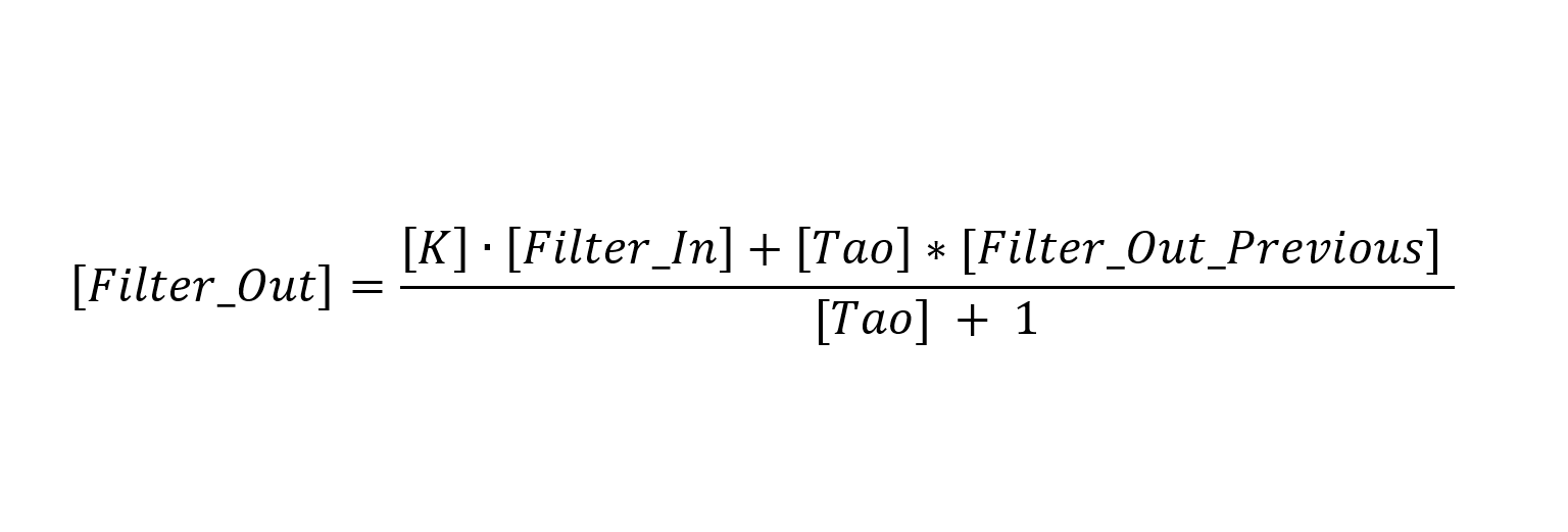
Normally this is all the bang-bang functionality, but we have added a feedback inner loop at the on/off output through a first order filter. This filter is implemented mathematically in the algorithm.
This first order filter (FOF) will receive the status of the bang-bang (BB) (hysteresis) output block that is a 1 (one) or 0 (cero) depending if the output is on or off. The result will be a capacitance charge or discharge depending on the state of the Bang-Bang block output. The tendence of the FOF output will be K when the BB output is on and will tend to cero when the output is off.
The output of the FOF is subtracted of the error [e] producing a reduced [e2] that will tend to K, this means that when the error (e=SP-PV) is greater for enough time, e2 will tend to e-Kr, therefore e2 will be greater than H turning the output of the BB to on.
The final control element will stay open until the plant reaches the difference stated by e2 ≤ L the output of the BB will turn off even when the plant has not yet reached the Setpoint, but then the feedback filter will begin a discharge provoking an increase on e2. The discharge will continue until e2 reaches H that will turn again the output of BB.
The process will continue to cycle between on/off until the PV reaches SP.
Tunning the Bang-Bang
Tunning method is quite intuitive. But is best to begin with small gain in the feedback filter and few units of error to turn on the control and few units to turn off the control. It can begin centered over cero. For example, start with [H = 0.5% of the control variable] and [L=- 0.5% of the control variable]. Make K=0 to see how the system reacts to a pure bang-bang.
The sample time should be equal to the periodic function call for the Bang-Bang function. This parameter is important because it will determine the system timing for the following steps.
Check the overshoot after the system stabilizes, make [K] equal to overshoot and [Tao] equal to the dead time (t0) to estimate this time (does not have to be precise) measure the time between the output of the actuator activates and when you can see a perceivable change of 0.5% in the control variable.
This will set up the Bang-Bang for the first pass tunning.
By observing the system capacity, you may reduce the gap between [H] and [L] to reduce magnitude of the fluctuations around the set point [SP].
You can also reduce or increase the on/off period by modifying [Tao] on the control. This will enhance the precision of the system output but will create and increase of on/off cycles in the actuator.
Be aware that if the actuator has a mechanical operation such as a relay, contactor or solenoid valve, the life of the actuator will be inverse of the number of on/off cycles, so you will need to make a trade off among life of the actuator and precision of the control.
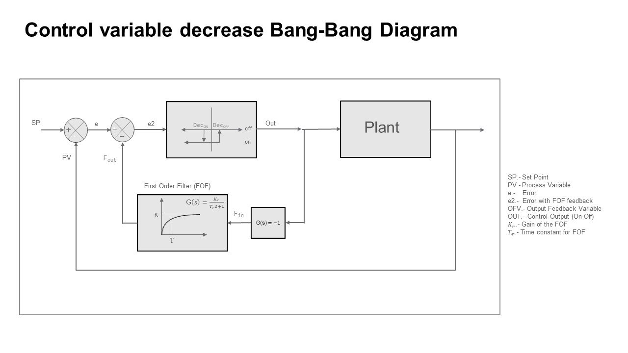
Cooling Bang-Bang (Actuator to decrease the control variable)
The algorithm to decrease the control variable such as cooling in a heated tank or pressure release valve in a pressure tank is very similar to the heating diagram but with some changes as shown in figure 2: