Loading
Create what's next
Automation Fair registration is open! Make plans today to join us in Chicago, November 17-20.
Register Now
Chevron RightChevron Right
Load sharing | Torque | PowerFlex 755T | TLink | FO Module

Application and Configuration of a Torque Follower System with PowerFlex 755T- and the use of the TLink Module (FO Module)

Configure a load sharing application using a torque follower configuration. Load sharing is a system in which multiple drives and motors are coupled and used to a load. - [Deploy Time: 60 Minutes]
Electric motor with gear driven conveyor belt.A close-up image of a blue machine, emphasizing the motor and its engineering features in sharp detail.
On This Page:
  • What is this for?
  • Installation guide
Innovation Center Home

What is this for?

The purpose of this document is to provide guidelines how to setup a load sharing application using a torque follower setup.

Load sharing is a term used to describe a system where multiple drives and motors are coupled and used to run one mechanical load.

The following assumptions are made:

  • Drives and motors are properly sized for the application
  • The drives are at factory default settings
  • The motors are equipped with rugged feedback devices
  • Drives are equipped with TLink option module and feedback cards
powerflex-755t-torque-follower-application_Fig 1.png

Downloads

Please note: You will need to agree to the Terms & Conditions for each download.

Download files ›
Legal Disclaimer Acceptance. ROCKWELL AUTOMATION WILL PROVIDE ACCESS TO ROCKWELL PRODUCTS (BEST PRACTICES, APPLICATIONS AND KNOWLEDGE) ON THE CONDITION THAT YOU ACCEPT AND COMPLY WITH THE FOLLOWING TERMS AND CONDITIONS. YOU ACCEPT AND AGREE TO BE BOUND BY THE TERMS OF THIS AGREEMENT BY DOWNLOADING, INSTALLING, COPYING, OR OTHERWISE USING PRODUCTS. IF YOU ARE ACCEPTING THESE TERMS ON BEHALF OF ANOTHER PERSON, COMPANY, OR OTHER LEGAL ENTITY, YOU REPRESENT AND WARRANT THAT YOU HAVE FULL AUTHORITY TO BIND THAT PERSON, COMPANY, OR LEGAL ENTITY TO THESE TERMS. IF YOU DO NOT AGREE TO THESE TERMS, DO NOT DOWNLOAD, INSTALL, COPY, ACCESS, OR USE THE PRODUCTS, SOFTWARE AND/OR CLOUD SERVICES. 1. Rockwell Automation retains full ownership and title to all Products and related documentation. No rights or licenses are granted other than those set forth in this Agreement. Company grants to Rockwell Automation a non-exclusive, worldwide, royalty-free, perpetual, non-revocable license to use any feedback Company provides regarding the Products, even if Company has designated the feedback as confidential. Rockwell Automation will be entitled to use the feedback without restriction or compensation to Company. 2. Company may not lease sub-lease, assign, license, sub-license or otherwise transfer any of the Products without the prior written consent of Rockwell Automation. Company may not assign or otherwise transfer access rights to the Products without the prior written consent of Rockwell Automation. Any reverse assembly, reverse engineering, decompilation, and creation of derivative works based on the Products by Company is prohibited. 3. Company acknowledges that Products provided under this Agreement are Rockwell Automation’s Confidential Information and are covered by effective or pending copyrights, patents, trademarks and/or trade secrets of Rockwell Automation, and Company agrees to maintain confidentiality by not disclosing Products or documentation to any third party without the prior written consent of Rockwell Automation and to protect the confidentiality of the Products as it would Company’s own confidential information. Company agrees that its obligation of confidentiality under this paragraph shall survive expiration or termination of this Agreement. 4. Company agrees that Products provided under this Agreement are prototypes and examples and its application and results may vary depending on each customer and project conditions. Rockwell Automation do not warranty the same results. This Agreement shall in no way be construed as a commitment by Rockwell Automation at any time to manufacture and/or offer Products for sale. There is no explicit or implicit service level agreement associated with using the Products. Rockwell Automation does not warrant that the functions contained in the Products will meet Company’s requirements. Company agrees to use all Products only in accordance with the instructions and only for the intended usages identified in the documentation. 5. EXCLUSION OF WARRANTIES AND LIMITATION OF LIABILITY. THE PRODUCTS ARE PROVIDED "AS IS". ROCKWELL AUTOMATION DISCLAIMS ANY AND ALL WARRANTIES, EXPRESS, IMPLIED OR STATUTORY, INCLUDING WITHOUT LIMITATION ANY WARRANTIES OF MERCHANTABILITY OR FITNESS FOR A PARTICULAR PURPOSE. ROCKWELL AUTOMATION EXPLICITLY DISCLAIMS ALL WARRANTIES OF NON- INFRINGEMENT AND EXPRESSLY DOES NOT WARRANT THAT THE PRODUCTS, IN WHOLE OR IN PART, WILL BE ERROR FREE OR FREE FROM SECURITY VULNERABILITIES. IN NO EVENT SHALL ROCKWELL AUTOMATION BE LIABLE FOR (i) LOST PROFITS, LOST SAVINGS, DOWNTIME, SPECIAL, INDIRECT OR CONSEQUENTIAL DAMAGES OF ANY KIND, OR (ii) ANY PERSONAL INJURY, PROPERTY DAMAGE OR ENVIRONMENTAL DAMAGE ARISING OUT OF OR IN CONNECTION WITH THIS AGREEMENT, WHETHER IN AN ACTION IN CONTRACT, STRICT LIABILITY OR IN TORT INCLUDING NEGLIGENCE. 6. COMPANY AGREES TO INDEMNIFY AND HOLD ROCKWELL AUTOMATION HARMLESS FROM ALL COSTS, AWARDS, DAMAGES, EXPENSES AND FEES (INCLUDING ATTORNEYS FEES) RESULTING FROM OR RELATED TO ANY THIRD-PARTY CLAIMS (INCLUDING EMPLOYEES AND AGENTS OF COMPANY) AGAINST ROCKWELL AUTOMATION, ITS DISTRIBUTORS, AGENTS, OFFICERS, DIRECTORS OR EMPLOYEES FOR PERSONAL INJURY (INCLUDING DEATH), PROPERTY DAMAGE OR ENVIRONMENTAL DAMAGE RELATED TO OR RESULTING FROM THE USE OF THE PRODUCTS. 7. In the event a Product is exported, Company agrees to comply with all applicable United States Export Control Law and Regulations, and the applicable export control laws of other countries. This Agreement shall be governed by the laws of the state of Wisconsin. This Agreement is the complete and exclusive Agreement between Rockwell Automation and the Company, and supersedes all prior agreements, whether written or oral, relating to the Products.

Need Help?

If you need help with an application or have feedback from the Innovation Center, please contact us.

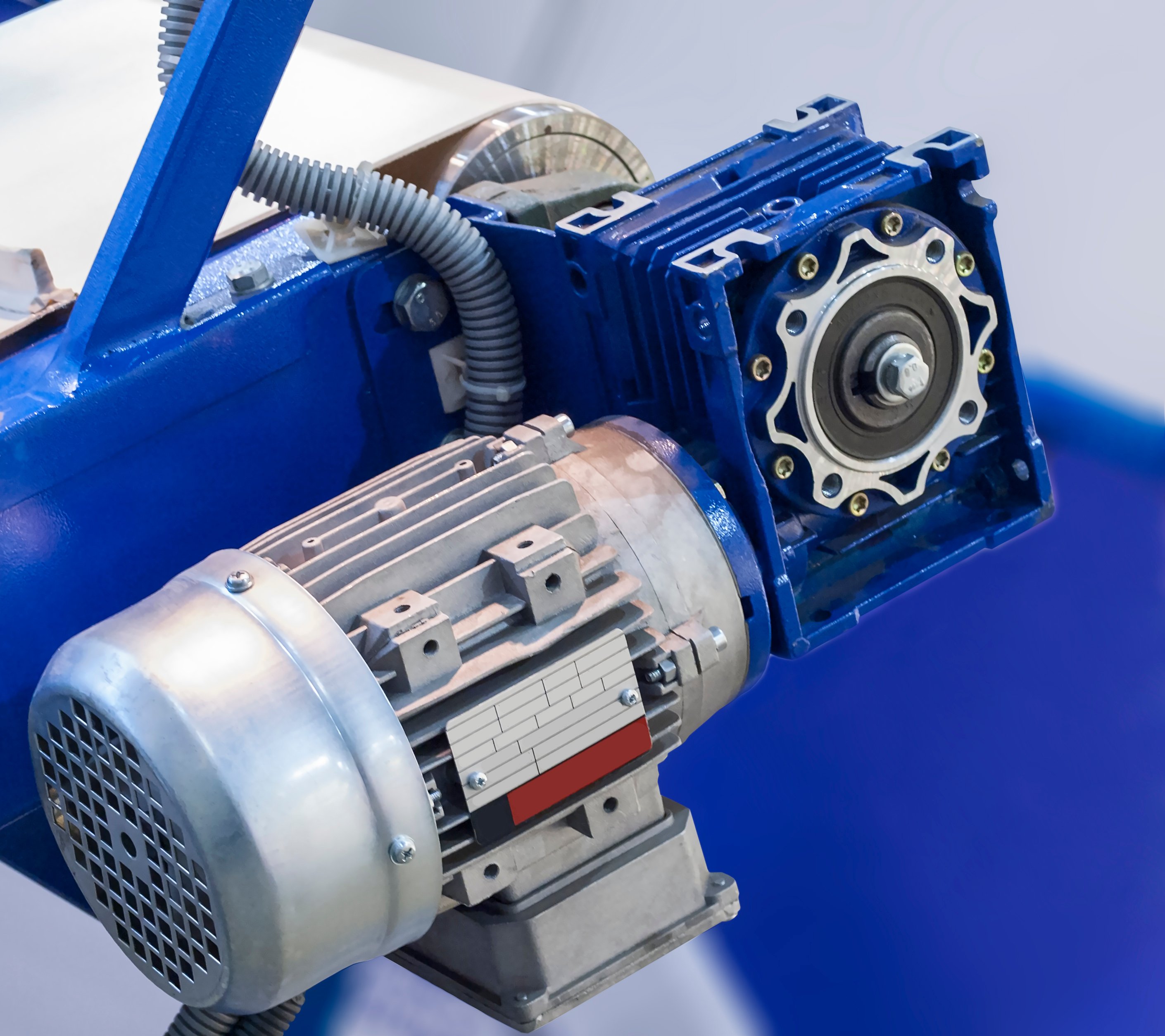
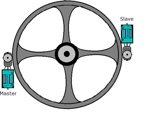
The example is based on a large diameter bull gear with two motors. The motors are coupled via tooth sprockets and gearboxes.

This creates a rigid connection between the motors, ideal for a torque follower setup.

The torque follower (also known as master-slave) is a type of load sharing setup when we use one master drive in speed regulation and one follower drive in torque regulation.

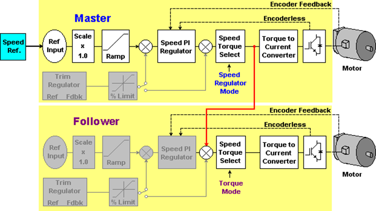
The torque command generated by the master’s speed loop is transmitted to the follower drive to be used as torque reference.

powerflex-755t-torque-follower-application_Fig 2
 

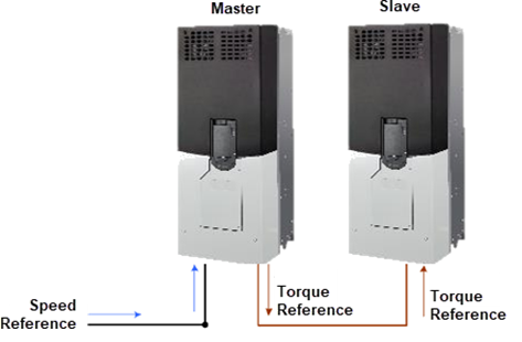
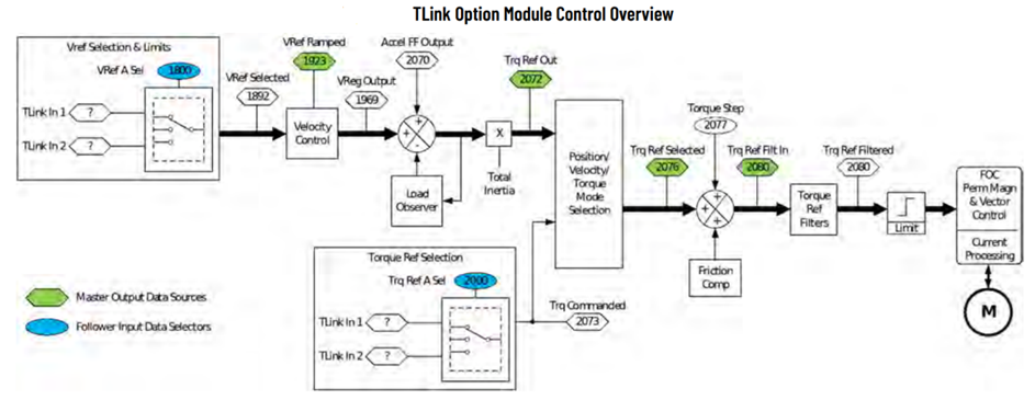
A torque follower setup makes two or more motors act as 1 big motor. See below torque follower block diagram.

powerflex-755t-torque-follower-application_Fig 3
 

In this example the torque reference is transferred from the master drive to the follower drive via TLink option module.

powerflex-755t-torque-follower-application_Fig 4

Is this helpful?
If you are working with systems involving multiple motors coupled to a single load, this document will be very useful to you in setting up an efficient and effective control strategy.


How can I get this working?

  • Hardware
    • Logix 5580-1756-L8SE Control
    • PowerFlex 755T Flux Vector Tuning
    • TLink (FO Module) - 20-750-TLINK-FOC-5
    • Incremental Encoder Board 20-750-ENC-1
  • Software
    • Studio5000 (V36)
  • Previous knowledge:
    • Basic knowledge of Studio5000
    • Basic knowledge of PowerFlex 755T.


References documents

  • PowerFlex Drives with TotalFORCE control Quick Start, Rockwell Automation Publication 750-QS100D-EN-P - January 2023.
  • PowerFlex Drives with TotalFORCE control Programming Manual, Rockwell Automation Publication 750-RM100C-EN-P - August 2022.
  • PowerFlex 755T Flux Vector Tuning Application Technique, Rockwell Automation Publication 750-AT006D-EN-P - January 2022.
  • TLink Option Module User Manual Original Instructions, Rockwell Automation Publication 750COM-UM100A-EN-P - June 2021.

Installation Guide 

 
  • Step 01


    Pasos de configuración VDF


    1. General Settings

    In this example both drives are equipped with a 20-750-TLINK-FOC-5 (Fiber 5 m) Module located in the Port 4, and a 20-750- ENC-1 Incremental Encoder card in the Port 5.

    The following settings apply to both drives.

    - 0:65 [Pri Mtr Ctrl Mode] = 4 “Induction FV”. This selects motor control mode as Induction Flux Vector.
    - Enter motor data parameters in 10:400 - 10:407.
    - 10:1000 [Pri Vel Fb Sel] = 5:4 [Encoder Feeback]. This selects incremental encoder as motor feedback source.
    - Enter encoder resolution in 5:2 [Encoder PPR].


    2. Master Drive setup

    • 10:30 [PsnVelTrq Mode A] = 1 “Velocity Reg”. This selects control mode for velocity regulation.
    • Select speed reference source in 10:1800 [Vel Ref A Sel]
    • Set the speed limits and ramp rates according to the application.
      • 10:1392 [Max Speed Fwd] 
      • 10:1393 [Max Speed Rev] 
      • 10:1915 [VRef Accel Time 1]
      • 10:1917 [Vref Decel Time 1]
    • 10:930 [Direction Mode] = 1 “Bipolar”.This selects the Velocity reference can be positive and negative.
    • 10:2020 [LdObs Mode] = 1 “LdObs Only”.
    • This is the recommended Load Observer setting for velocity mode applications. For more information about Load Observer feature see PowerFlex 755T Flux Vector Tuning, publicación 750-AT006.
    • Set output torque limits according to machine design, drive and motor sizing. In this example +/-150%.
    • 10:2083 [Torque Limit Pos] = 150%
    • 10:2084 [Torque Limit Neg] = -150%
     

    3. TLink Option Module Master Drive setup


    • 4:1 [TLink Mode] = 1 “Mode A”. Master sends 2 words synchronized 50 mµ updates.
    • 4:2 [TLink Role] = 0 “Master”. Sets TLink role for the drive, Master sources data to nodes.
    • 4:201 [TLink Out Sel 1] = 0 “Trq Ref Out”. Selects the torque reference output.
    • 4:202 [TLink Out Sel 2] = 3 “VRef Ramped”. Selects the ramped velocity reference output.
     

    4. Slave Drive setup

    • 110:30 [PsnVelTrq Mode A] = 2 “Torque Reg”.  This selects control mode for torque regulation.
    • 10:2000 [Trq Ref A Sel] = 4:203 [TLink In 1]. This gets Torque Ref from master.
    • 10:1800 [VRef A Sel] = 4:206 [TLink In 2]. This gets ramped velocity reference from master.
    • 10:2020 [LdObs Mode] = 0 “Disabled”. This is the recommended Load Observer setting for torque mode applications.
    • Set output torque limits according to machine design, drive and motor sizing. The slave drive values are set slightly higher as the command values are clamped by the master drive.
    • 10:2083 [Torque Limit Pos] = 155
    • 10:2084 [Torque Limit Neg] = -155%


    5. TLink Option Module Slave Drive setup 

    • 4:1 [TLink Mode] = 1 “Mode A”. slave receive 2 words synchronized 50 mµ updates.
    • 4:2 [TLink Role] = 0 “Slave”. Sets TLink role for the drive, Slave consumes data from the master.
    • 4:3 [TLink Status] = 1 “Tx Active”. Verify transmission of data by master (TLink option module in master drive)
    • 4:3 [TLink Status] = 3 “In Sync”. Verify that slave drive is synchronized to the master drive in slave (TLink option module in slave drive)
     
  • Step 02


    Tuning Steps

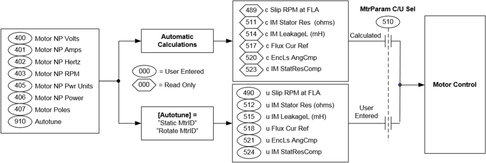
    Tuning is critical working in Flux Vector control mode. We will use the Autotune function to measure motor characteristics. Autotune is composed of several individual tests, each of which is intended to identify one or more motor parameters. These tests require motor nameplate information to be entered into the drive parameters. We can run all the tests in the parameter 10:910 [Autotune].


    These are the recommended steps:

    1- Enter motor data parameters in 10:400 – 10:407.

    2 - Run 10:910 [Autotune] = 1 “Direction”. This allows you to determine if the motor rotates in the desired direction. Also allows you to check if encoder feedback count increases in value for a forward velocity command.

    3 - Measure the motor electrical parameters:

    • Set 10:510[MtrParam C/U Sel] = 1 “User Entered”
    • Run 10:910 [Autotune] = 3 “Rotate MtrID” to measure the motor electrical parameters. It initiates motion and rotates the load. To obtain the most accurate measure of motor flux current, disconnect the load for this test.
    • If you cannot initiate motion to rotate the load, then run 10:910 [Autotune] = 2 “Static MtrID” to measure the motor electrical parameters.
    powerflex-755t-torque-follower-application_Fig 5.png


    4 - Set the current regulator bandwidth 10:445 [VCL CReg BW]

    • 125 when 10:425 [PWM Frequency] = 1.33 kHz
    • 250 when 10:425 [PWM Frequency] = 2 kHz
    • 375 when 10:425 [PWM Frequency] = 4 kHz


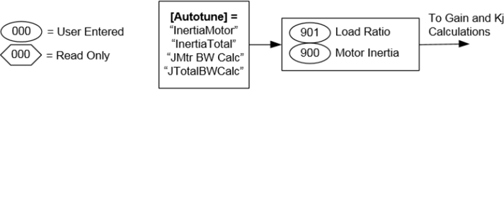
    5 - Run 10:910 [Autotune] = 4 “InertiaMotor” to measure the motor inertia. This test initiates momentary motor rotation to measure and update 10:900 [Motor Inertia].


    This test is only an option if the load can be disconnected to run the test. If the load cannot be disconnected, you should enter the value manually in 10:900 [Motor Inertia].


    6 - In the master drive, run 10:910 [Autotune] = 5 “Inertia Total”. This test initiates momentary rotation of the motor and load to measure total inertia and calculate 10:901 [Load Ratio]. After selecting this value, you must issue a start command to begin the test. Perform this test with the load connected to the motor.


    10:900 [Motor Inertia] and 10:901 [Load Ratio] are used to calculate the torque scaler Kj, an internal parameter that compensates for the effects of inertia and affects overall tuning. Load Ratio is also used to calculate controller gains.

    powerflex-755t-torque-follower-application_Fig 6.png

    Since the application will be controlled by 2 load sharing motors, the Load Ratio of the Master drive measured during the test can be divided by 2.


    7 - In the master drive, run 10:910 [Autotune] = 6 “BW Calc”. The bandwidth calculation test calculates control loop gains and dynamic limits.

    8 - Run the master drive and adjust system bandwidth in 10:906 [System BW] if necessary. Decreasing system bandwidth stabilizes the system and increasing it improves performance. Typically, high gain results in a quicker response time, but excessive gain causes system instability.


    For more information about tuning see PowerFlex 755T Flux Vector Tuning, publication 750-AT006.

  • Step 03


    Signal Checks and Operation Steps

    1. Signals Checks

    Run the master motor (only) up to nominal speed. Master Drive: Check 10:2087 [Trq Ref Limited] during acceleration.


    2. Operation

    To start the torque follower application

    • Start the follower drive first. Since the master drive is not running the follower drive is not receiving any torque reference. At this stage the motor is fluxed and ready to go.
    • When the slave drive is running start the master drive. The speed regulator of the master drive generates a torque command which is used in the master drive and transferred to the follower drive. Both drives and motor will take an equal share of the load and act as 1 big one.


    To stop the torque follower crusher application

    • Stop the master drive first. The master drive will ramp down its speed and send out a negative torque command to the slave drive to assist. The torque command values can be clamped by the bus regulator reducing the amount of regenerative energy.
    • Stop the follower drive once the master drive is not active anymore. See Drive status word via the communication interface or via 10:354 [Motor Side Sts 1] bit 1 [Active].


    When a drive is faulted

    • If the master drive is faulted the follower won’t receive any torque reference. In this condition the slave drive would almost coast to a rest. At this stage there are two options:
    • The fault can be cleared, and the master drive can be restarted, the speed will be picked up immediately by the motor encoder (no need for flying start activation).
    • The slave drive can be stopped. To make sure the slave drive stops with a controlled deceleration ramp verify that bit 1 [Torq Mode stop] of 10:40 [Motor Cfg Options] is set.
    • - If the slave drive is faulted the master drive is taking the full load. It may reach current limit and potentially stall. The drive could then trip on motor overload. The master drive can be stopped.


  • Step 04


    Load Logix program into the controller Steps


    1 - On the Studio 5000 development software we open the program “Torque_Follower_with_TLink”, the following image is then displayed, where the controller, an analog and a digital card, as well as the Ethernet card where the PowerFlex 755TS Drives will be part of the network are already added.

     
    powerflex-755t-torque-follower-application_Fig 7.png
     

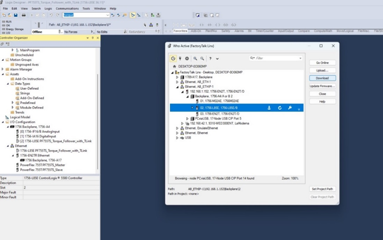
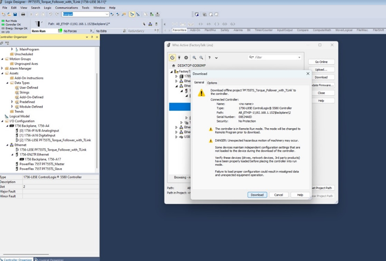
    2 - On the menu bar, click on “communication” and choose “download” from the options that appear, then click again on the button in the window that opens, as shown in the following image.

    powerflex-755t-torque-follower-application_Fig 8.png
     

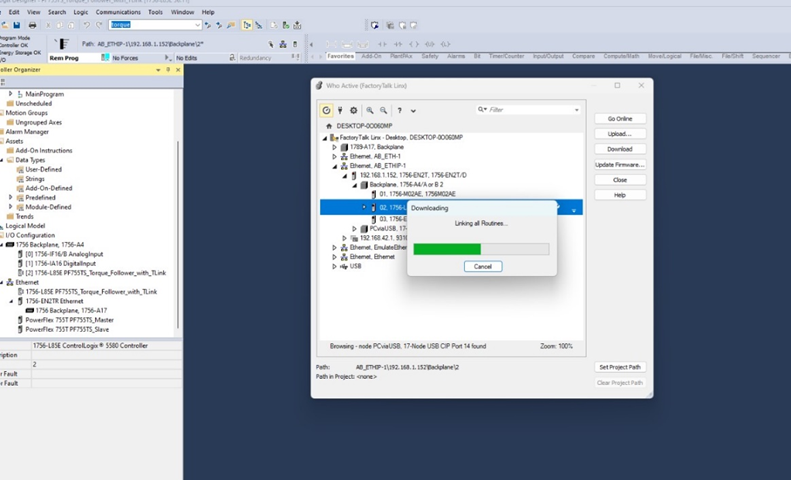
    3 - We wait for the program to download to the controller

    powerflex-755t-torque-follower-application_Fig 9.png
     

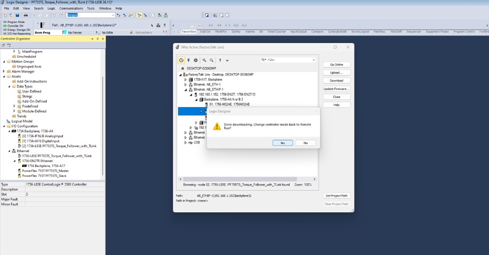
    4 - Finally we click on the Yes button on the window that appears after the program is loaded into the controller, this, to change the controller mode to “Remote Run”

    powerflex-755t-torque-follower-application_Fig 10.png


Application and Configuration of a Torque Follower System with PowerFlex 755T- and the use of the TLink Module (FO Module)

Version 1.0 - December 2024

Have a general inquiry?

Rockwell Automation and our partners offer exceptional industry knowledge to help design, implement, and support your automation investment.

Contact Rockwell Automation
  1. Chevron LeftChevron Left Rockwell Automation Home Chevron RightChevron Right
  2. Chevron LeftChevron Left Sup... Chevron RightChevron Right
  3. Chevron LeftChevron Left Pro... Chevron RightChevron Right
  4. Chevron LeftChevron Left Downloads Chevron RightChevron Right
  5. Chevron LeftChevron Left Innovation Center Chevron RightChevron Right
  6. Chevron LeftChevron Left Application and Configuration of a Torque Follower System with PowerFlex 755T- and the use of the TLink Module (FO Module) Chevron RightChevron Right
Please update your cookie preferences to continue.
This feature requires cookies to enhance your experience. Please update your preferences to allow for these cookies:
  • Social Media Cookies
  • Functional Cookies
  • Performance Cookies
  • Marketing Cookies
  • All Cookies
You can update your preferences at any time. For more information please see our Privacy Policy
CloseClose