- FactoryTalk Design Studio Help
- Programs, tasks, and routines
- Add-On Instructions
- FactoryTalk Design Studio Code editor
- Instructions
- Instruction set
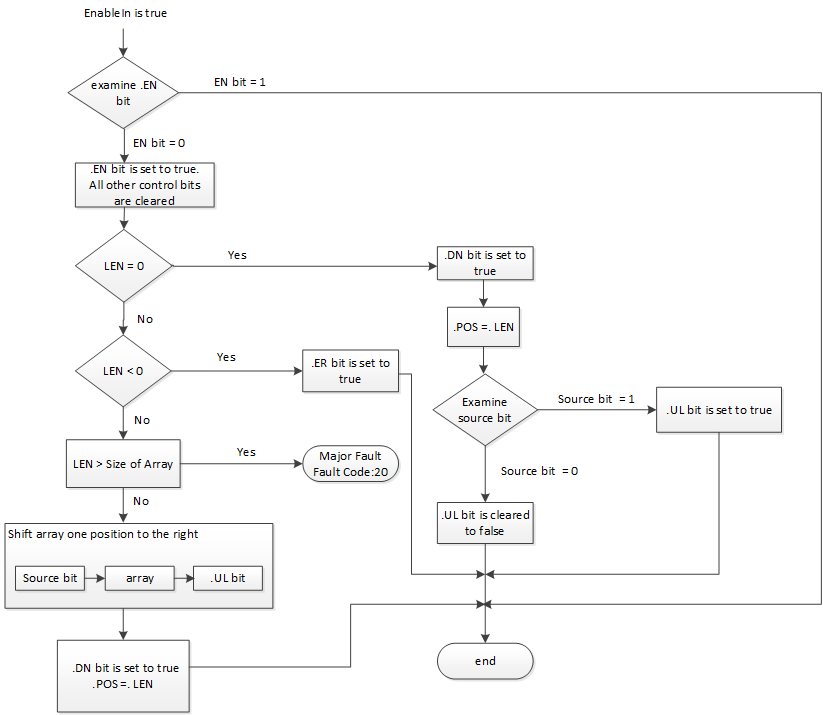
Bit Shift Left (BSL)
The BSL instruction shifts the specified bits within the Array one position left.
When enabled, the instruction unloads the uppermost bit of the specified bits to the .UL bit, shifts the remaining bits one position left, and loads Bit address into bit 0 of Array.
IMPORTANT:
You must test and confirm that the instruction does not change data that you do not want it to change.
The BSL instruction operates on contiguous data memory. The data is constrained by the specified member.
In this transitional instruction, the relay ladder toggles the rung-condition-in from false to true for the instruction to execute.
Available Languages
Ladder Diagram
_v1.png/_jcr_content/renditions/original)
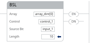
Operands
Ladder Diagram
Operand | Type | Format | Description |
|---|---|---|---|
Array | DINT ARRAY | tag | Array to modify specify the first element where to begin the shift |
Control | CONTROL | tag | Control structure for the operation |
Source Bit | BOOL | tag | Bit to shift into the vacated position. |
Length | DINT | immediate | Number of bits in the array to shift |
CONTROL Structure
Mnemonic | Data Type | Description |
|---|---|---|
.EN | BOOL | The enable bit indicates the BSL instruction is enabled. |
.DN | BOOL | The done bit is set to indicate that bits shifted one position to the left. |
.UL | BOOL | The unload bit is the instruction’s output. The .UL bit stores the status of the bit that was shifted out of the range of bits. |
.ER | BOOL | The error bit is set when .LEN < 0. |
.LEN | DINT | The length specifies the number of array bits to shift. |
Affects Math Status Flags
No
Major/Minor Faults
A Major Fault Occurs If | Fault Type | Fault Code |
|---|---|---|
The LEN exceeds the size of the array | 4 | 20 |
See Common Attributes for operand related faults.
Execution
Ladder Diagram
Condition/State | Action Taken |
|---|---|
Prescan | The .EN bit is cleared to false. The .DN bit is cleared to false. The .ER bit is cleared to false. The .POS value is cleared |
Rung-condition-in is false | The .EN bit is cleared to false. The .DN bit is cleared to false. The .ER bit is cleared to false. The .POS value is cleared. |
Rung-condition-in is true | See BSL Flow Chart (True). |
Postscan | N/A |
BSL Flow Chart (True)
Examples
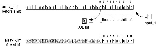
Example 1
When enabled, the BSL instruction starts at bit 0 in array_dint[0]. The instruction unloads array_dint[0].9 into the .UL bit, shifts the remaining bits, and loads input_1 into array_dint[0].0. The remaining bits (10-31) are invalid.
Ladder Diagram
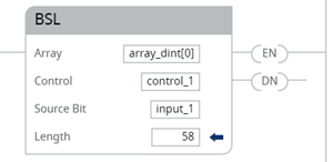
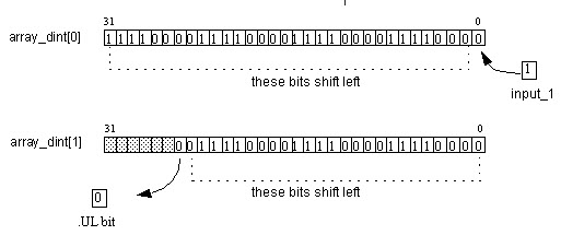
Example 2:
When enabled, the BSL instruction starts at bit 0 in array_dint[0]. The instruction unloads array_dint[1].25 into the .UL bit, shifts the remaining bits, and loads input_1 into array_dint[0].0. The remaining bits (31-26 in array_dint[1]) are invalid.
Provide Feedback