Add dynamic graphical objects
Configure dynamic graphical objects, referred to as dynamic links, that are typical to HMI applications.
An HMI application contains graphical objects that represent different physical objects that are being managed by the application. Each graphical object has a set of configurable properties that represent different settings, inputs, outputs, and other data. Some properties are derived by by setting the value of a property based on the value of another property called using a
dynamic link
.To explore these concepts:
- We will connect an LED to a switch to set its on/off status.
- We will connect the same LED to a spin-box, through aconverter, to set its color.
To remember
- When two variables of the same type are linked, adynamic linkis created.
- When two variables of a different type are linked, it is necessary to set up one or more converters: then anadvanced dynamic linkis created.
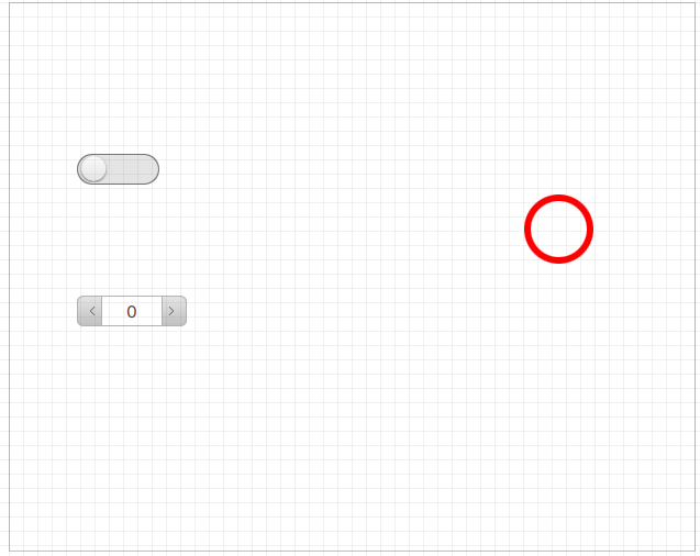
This is the final result:
Step #1: Add graphical objects
We will add the objects in the first navigable panel, i.e.
Page1 (type)
:- Double-clickPage1 (type): the panel opens in the editor.
- To add the LED, inProjectright-clickPage1 (type), then selectNew>Basic controls>LED:LED1appears inPage1 (type)and in the objects editor.
- To add the switch, inProjectright-clickPage1 (type), then selectNew>Basic controls>Switch:Switch1appears inPage1 (type)and in the objects editor.
- To add the spin box, inProjectright-clickPage1 (type), then selectNew>Basic controls>Spin box:SpinBox1appears inPage1 (type)and in the objects editor.
- In the editor, drag the three objects to the desired position. Below is an example:
Step #2: Associate the LED status with the switch status
To turn the LED on/off with a switch, we will insert a dynamic link between the activation states of the two objects:
- In theLED1properties, click
 next to the Activeproperty: the dynamic links window opens which displays all the project elements and their properties.
 - In the window, insideSwitch1select theActivevariable and pressSelect: the value of theActiveproperty ofLED1is the path to the switch property.
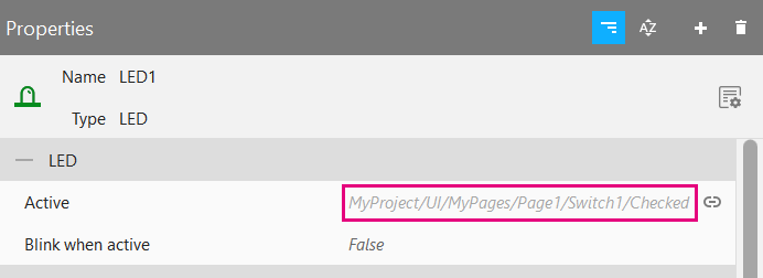
In this way, the LED status depends on the switch status. In this case, the two linked properties contain a value of the same type (Boolean). For this, a simple dynamic link is sufficient. Find out more about dynamic links: Dynamic Links.
Step #3: Associate the LED color with the spin-box value
In this phase, the link is between two properties that contain values of different types: number and color. For this, a
converter
has to be used, which transforms the input data into another type of data. Here we will use a Key-Value converter to transform the spin-box numerical data into data of color type for the LED.- Select the LED and click next to its Colorproperty, then clickAdvanced: the editor of the dynamic link for theColorproperty opens.
- To add the converter, click
 > Key-Value converter: the block of the Key-value converter appears.DynamicLink Sourceindicates the input variable to the converter, which transforms it to supply its value to theColorproperty.
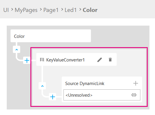
- To set the converter input, in our case the spin-box value, inDynamicLink Sourceclick
 , then in Spinbox1selectValue, then clickSelect.
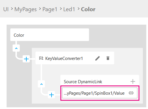
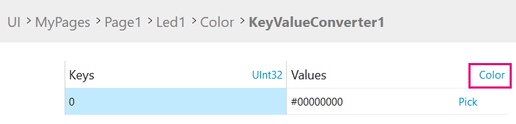
- To set the conversions to perform, inKeyValueConverter1click
 : the conversion table appears in the object editor.
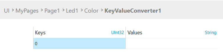 Each row defines a key/value pair: in this caseKeyis the spin-box value,Valueis the LED color.
 - For the conversion, the correct data types must be set forKeyandValuevisible in the header; in particularValuemust be of color type. To do it, in theValuecolumn clickString: a list with the most common data types appears.
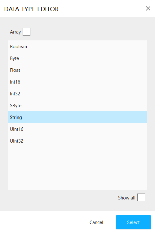
- To display all the available data types, selectShow All, then chooseColorand clickSelect.
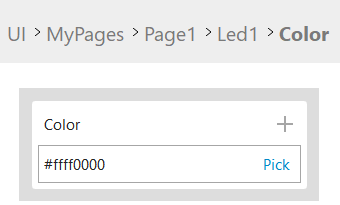
- To change the color associated with the existing0key, clickPickin the related cell, select the color and clickSelect.
- To set other key/value pairs, click
 and change the values. Below is an example:
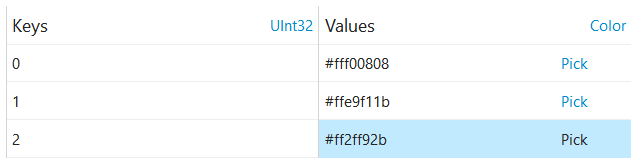
Find out more about the Key-Value converter: Key-Value converter.
Provide Feedback