- Studio 5000 Logix Designer
- Tasks, programs, and routines
- Add-On Instructions
- Controller Organizer
- Logical Organizer
- Alarms
- Tag-based alarms
- Tag Editor and Data Monitor
- Configure settings for Tag Editor and Data Monitor
- Equipment phases
- Equipment Sequences
- Equipment Sequence Diagrams
- Ladder Editor
- Structured Text Editor
- Sequential Function Chart Editor
- Define the steps of an SFC process
- PlantPAx instruction properties
- Controller Properties
- Editing Controller Properties
- Controller Security
- Source Protection
- License Source Protection for Routines and Add-On Instructions
- Module Information
- 1756 ControlLogix I/O Modules
- Instruction Set
Safe Operating Stop (SOS)
This instruction only applies to the
Compact GuardLogix
5380 and GuardLogix
5580 controllers.The Safe Operating Stop (SOS) instruction monitors the speed or position of a motor or axis to ensure the deviation from standstill speed or position, is not more than a defined amount.
Available Languages
Ladder Diagram

Function Block
This instruction is not available in function block.
Structured Text
This instruction is not available in structured text.
Safe Operating Stop Application
Safe Operating Stop is used with a CIP safety drive that supplies the speed and position of a motor or axis and a Safe Feedback Interface (SFX) instruction to scale the feedback. During operation, the SOS instruction signals with the SOS Standstill output when the motor speed is at or below the Standstill Speed or position, depending on the Mode input.
Operands
IMPORTANT:
Unexpected operation may occur if:
- Output tag operands are overwritten.
- Members of a structure operand are overwritten.
- Structure operands are shared by multiple instructions.
- The rung in condition is no longer true
- An instruction fault has occurred
WARNING:
ATTENTION:
The SOS Safety Control structure contains internal state information. If any of the configuration operands are changed while in run mode, accept the pending edits and cycle the controller mode from Program to Run for the changes to take effect. The following table provides operands used for configuring the instruction.
Operand | Data Type | Format | Description |
|---|---|---|---|
Safety Control | SAFE_OPERATING_STOP | tag | Data structure required for proper operation of instruction. |
Restart Type | list item | This input selects the Restart Type for the instruction. MANUAL (0) A 0 to 1 transition of the Reset input is required after Request has been removed to enable the instruction to operate. AUTOMATIC (1) The instruction will reset when the Request has been removed and no fault is present [FP] = OFF(0). Once reset, the instruction will be able to operate.  ATTENTION: Only use Automatic Restart in applications where it is determined that no unsafe conditions occur from its use. | |
Cold Start Type | list item | This input selects the behavior when applying controller power or a controller mode change to Run. MANUAL (0) A 0 to 1 transition of the Reset input is required with the Request removed to enable the instruction to operate. AUTOMATIC (1) The instruction resets when the Request has been removed. |
The following table explains the instruction inputs.
Operand | Data Type | Format | Description |
|---|---|---|---|
Mode | SINT | immediate tag | This operand selects speed or position checking Range: 1 or 2. 1: Position Check 2: Speed Check |
Check Delay | INT | immediate tag | This operand defines the delay time between the SOS function request and the start of standstill monitoring. Range: 0 to 32767 Units: milliseconds (Ms) |
Standstill Speed | REAL | immediate tag | This input sets the maximum speed that is allowed before the instruction will fault after Check Delay expires. Range: >= 0 |
Standstill Deadband | REAL | immediate tag | This operand sets the maximum incremental deviation from the position that is captures at the expiration of Check Delay. If the maximum deviation is exceeded then this instruction will fault. Range: >= 0 |
Feedback SFX | SAFETY_FEEDBACK_INTERFACE | tag | This operand provides position and velocity data. Assign this operand to the SFX instruction Safety Control tag that is used by the SOS instruction. The following members of the SFX Safety Control tag are used: FeedbackSFX.FeedbackPosition Units: Feedback Counts FeedbackSFX.ActualSpeed Units: Postion Unit / Time Unit FeedbackSFX.PositionScalingOut Units: Feedback Counts / Position Unit |
Request | BOOL | tag | This operand enables the SOS function. ON(1): allows SOS function to begin monitoring. OFF(0): allows function reset according to Restart Type |
Reset 1 | BOOL | tag | This operand resets the SOS function. An OFF(0) to ON(1) transition resets the SOS function and Fault Present [FP] provided the Request is OFF(0) and any fault condition has been removed. The Reset Required [RR] output indicates when a reset is required to reset the function. |
1
ISO 13849-1 stipulates instruction reset function must occur on falling edge signals. To comply with ISO 13849-1 requirements, add the logic immediately before this instruction. Rename the Reset Signal tag in this example to the reset signal tag name. Then use the OSF instruction Output Bit tag as the instruction’s reset source.
This table explains instruction outputs. The outputs are external tags (safety output modules) or internal tags used in other logic routines.
Operand | Data Type | Description |
|---|---|---|
Output 1 [O1] | BOOL | ON(1): Indicates the instruction is executing and the function is not faulted. OFF(0): One of the following occurs: |
Reset Required [RR] | BOOL | ON(1): Indicates that an Reset is required to restart the instruction and or to clear faults. See Reset Input for Reset sequence. OFF(0): Normal operation under Automatic Restart operation. |
Fault Present [FP] | BOOL | ON(1): A fault is present in the instruction. OFF(0): The instruction is operating normally. |
Diagnostic Code | SINT | This output indicates the diagnostic status of the instruction. See Diagnostic Codes and Corrective Actions for specific codes and actions. |
Fault Type | SINT | This output indicates the type of fault that occurred. See the Fault Codes and Corrective Actions section for specific codes and actions. |
Check Delay Active | BOOL | ON(1): Indicates that Check Delay timer is active. |
Standstill Set Point | REAL | This output shows the position that was captured at the end of the Check Delay period. This position is the standstill position used in Position Check Mode. |
This table explains instruction outputs that are written to the user-specified tag.
Operand | Data Type | Format | Description |
|---|---|---|---|
SOS Active | BOOL | tag | The SOS instruction writes the SOS Active status to this tag. OFF(0): SOS not active ON(1): SOS active Tip: Assign the SOS Active operand to the SOS Active member of the safety output tag structure corresponding to the motion safety instance of the drive module. The corresponding Axis Safety Status updates automatically in the drive axis tag structure to enable coordination of the motion task with the safety task. |
SOS Standstill | BOOL | tag | The SOS instruction writes the SOS Standstill status to this tag. OFF(0): Speed or position not at standstill. ON(1): Speed or position is within standstill limits. Tip: Assign the SOS Standstill operand to the SOS Standstill member of the safety output tag structure corresponding to the motion safety instance of the drive module. The corresponding Axis Safety Status updates automatically in the drive axis tag structure to enable coordination of the motion task with the safety task. |
SOS Fault | BOOL | tag | The SOS instruction writes the SOS Fault status to this tag. OFF(0): Not Faulted ON(1): Faulted SOS Fault bit to be set to ON (1) state for the following fault type and corresponding condition:
An instruction input operand value is out of range.
Standstill deadband was exceeded while monitoring.
Standstill speed limit was exceeded while monitoring.
The feedback used for monitoring is not valid or the SFX instruction is not running when SOS is requested. Tip: Assign the SOS Fault operand to the SOS Fault member of the safety output tag structure corresponding to the motion safety instance of the drive module. The corresponding Axis Safety Faults tag updates automatically in the drive axis tag structure to enable coordination of the motion task with the safety task. |
IMPORTANT:
Do not write to any instruction output tag under any circumstances.
Affects Math Status Flags
No
Major/Minor Faults
None specific to this instruction. See Index Through Arrays for array-indexing faults.
Execution
Condition/State | Action Taken |
|---|---|
Prescan | The .01, .FP, .RR, .SOSActive, .SOSStandstill, .SOSFault, and .CheckDelayActive outputs are cleared to OFF(0). The Diagnostic Code output is set to 0. The Fault Type output is set to 1 |
Rung-condition-in is false | The .O1, .SOSActive, .SOSStandstill, and .CheckDelayActive outputs are cleared to OFF(0). If an instruction fault is present when rung went false the fault condition will be maintained and Diagnostic Code displayed. |
Rung-condition-in is true | The instruction executes. |
Postscan | N/A |
Operation
Normal Operation
The SOS function begins if it has been previously reset and the Request input is asserted ON(1). At this point the Check Delay Timer begins. When the Check Delay Timer expires Standstill monitoring begins. When the timer expires the current position is captured. The speed or position, provided by an SFX instruction, is compared to the Standstill Speed or Position Deadband according to the Mode. If the speed of the monitored axis exceeds the limit then the SOS function will Fault. After the Check Delay Timer expires and the function is not faulted, the Standstill output is set ON(1).
Position values used in the SOS instruction are in Position Units. Speed values used in the SOS instruction are in Position Units / Time Unit. A position unit is user defined according to the particular application and is configured in the SFX instruction. Time units are also configured in the SFX instruction and may be selected as seconds or minutes.
Pass-Through Tags
A Safe Motion Monitoring Drive has one or more motion axes that are controlled by a motion task. The Safe Motion Monitoring Drive also has one or more motion safety instances that support safety functions used in a safety task of a safety controller. Some of the tags associated with a drives motion safety instance are pass-through tags. The following table shows the pass-through tags and the corresponding axis tags for the SOS function:
SOS Instruction Output | Pass-Through Tags for Motion Safety Instance | Safe Motion Monitoring Drive Action | Axis Tag |
|---|---|---|---|
SOS Active | module 1 :SO.SOSActive[instance2 ] | updates tag | axis 3 .SOSActiveStatus |
SOS Standstill | module 1 :SO.SOSStandstill[instance2 ] | updates tag | axis 3 .SOSStandstillStatus |
SOS Fault | module 1 :SO.SOSFault[instance2 ] | updates tag | axis 3 .SOSFault |
1
module is the name for the drive module in Logix Designer I/O Configuration tree2
instance is 1 or 2 for dual axis drives otherwise null3
axis is the axis name in the Logix Designer Motion Group and is associated with module When assigning the SOS Active, SOS Standstill and SOS Fault outputs to the motion safety instance pass-through tags, the corresponding Axis Safety Status and Axis Safety Faults tags automatically update in the motion controller. The motion control task of motion controller reads the Axis Safety Status and the Axis Safety Faults tags to coordinate operation between the safety task and motion task. The following is a typical sequence of events:
- The safety application receives an input to hold an axis at standstill.
- The Safety application sets the Request input ON(1) to request the SOS function.
- The SOS instruction sets SOS Active output and writes the module:SO.SOSActive[instance] tag of the motion safety instance in the drive.
- The motion safety instance in the drive updates the Axis Safety Status tag read in the motion controller.
- The motion application stops the axis motion and holds the position or speed at zero
- When the SOS function detects SOS Standstill the SOS instruction writes module:SO.SOSStandstill[instance] tag of the motion safety instance of the drive.
- The motion application reads the Axis Safety Status tags and continues to hold the position or maintain zero speed.
Normal Operation, Automatic Restart
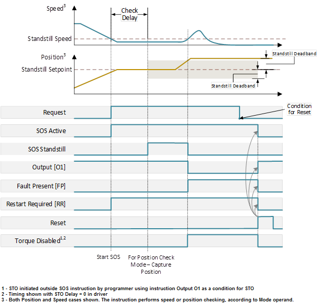
The following diagram shows Normal operation with Automatic Restart. After Check Delay expires the speed must stay below the Standstill Speed when in Speed Check mode and if in Position Check mode the Position must not deviate from the position captured at the end of the Check Delay Time by more than the Standstill Deadband. For automatic restart operation, the SOS function is reset when the Request is removed, OFF(0), provided no SOS faults have occurred.

Normal Operation, Manual Restart
When manual restart is configured, the SOS function must be reset before subsequent operation. The Reset Required output indicates that the Reset input must make an OFF(0) to ON(1) transition to reset the SOS function after the Request input is removed OFF(0). The following diagram shows normal operation with manual restart.

Faulted Operation
Faults for SOS may be for invalid configuration, or SFX Instruction Not Ready, described in Fault Codes and Corrective Actions. While monitoring is active, a fault occurs if the speed exceeds the standstill speed in Speed Check mode or if the position deviates from the initial position at the start of monitoring by more than the Standstill Deadband in Position Check mode. The diagram below shows speed and position faults.

Fault Codes and Corrective Actions
Fault Code | Description | Corrective Action |
|---|---|---|
1 | No fault | None |
2 | Invalid Configuration Fault |
|
3 | Standstill Position Fault | Ensure movement is within the Standstill Deadband after check delay time expires. |
4 | Standstill Speed Fault | Ensure speed is below the Standstill limit before check delay time expires. |
101 | Position Window Calculation Overflow Fault. The Position scaling from the Feedback SFX tag multiplied by the Position Window exceeds (2^31 – 1) |
|
102 | SFX Instruction Not Ready Fault | Ensure that the SFX instruction that supplies inputs to this SOS instruction is executing and not faulted before requesting SOS. |
Diagnostic Codes and Corrective Actions
Diagnostic Code | Description | Corrective Action |
|---|---|---|
0 | No diagnostic information. | None |
10 | Rung went false while SOS function was executing. | Make sure this instruction rung is enabled. |
20 | Mode value not valid. | Only values of 1 Speed Check or 2 Position Check are allowed. |
21 | Check Delay value not valid. | Check the Check Delay value to ensure it is >= 0 and <= 32767 |
22 | Standstill Deadband not valid | Standstill Deadband cannot be negative |
23 | Standstill Speed not valid | Standstill Speed cannot be negative |
Example

Provide Feedback