Specify the Communication Details
Set up a broadcast in ladder logic or structured text programs. In ladder logic, add a rung and click on the
MSG
property to access the Message Configuration
dialog box and set up a new message. In structured text, type MSG
(aMsg ) and then right-click the aMsg to open the Message Configuration
dialog box and configure the message.
NOTE:
Logix Designer versions 37 and later do not support controllers with serial ports. The
Broadcast
button appears only in Logix Designer versions 36 and earlier for controllers with a serial port.To configure a MSG instruction, specify the following on the
Communication
tab:
Specify a Path
The path shows the route that the message takes to get to the destination. It uses names from the I/O configuration of the controller, numbers that you type, or both. You can default the path by using the broadcast button, which must be enabled with the system protocol and message type.
If | Then |
|---|---|
The I/O configuration of the controller has the module that gets the message. | Browse to select the module. |
The I/O configuration of the controller has only the local communication module. | Browse to select the local communication module and type the rest of the path. |
The I/O configuration of the controller does not have any of the modules required for the message. | Type the path. |
TIP:
Also supported is THIS, which indicates a path to self. THIS is used to send an unconnected message to the controller.
Examples
The I/O configuration of the controller has only the local communication module:

To type a path, use the format:
port, next_address, port, next_address,
Where | Is | |
|---|---|---|
For this network | Type | |
Port | Backplane | 1 |
DF1 (serial, serial channel 0) | 2 | |
ControlNet | ||
EtherNet/IP | ||
DH+ channel A | ||
DH+ channel B | 3 | |
DF1 channel 1 (serial channel 1) | ||
Next_address | Backplane | Slot number of the module |
DF1 (serial) | Station address (0-254) | |
ControlNet | Node number (1-99 decimal) | |
DH+ | 8# followed by the node number (1-77 octal) For example, to specify the octal node address of 37, type 8#37. | |
EtherNet/IP | Specify a module on an EtherNet/IP network by using any of these formats:
| |
Broadcast Button
The
Broadcast
button is used with the serial port.- This functionality for RSLogix 5000 software, beginning with version 18, enhances the ability to define the route and message type that are required to send a message to its destination.
The
Broadcast
button, when enabled, allows you to default the path by selecting an available channel(s) in a combo box. The number of channels listed in the combo box depends on the current controller.By default, the
Path
button on the Communication
tab is active. Perform these steps to enable the
Broadcast
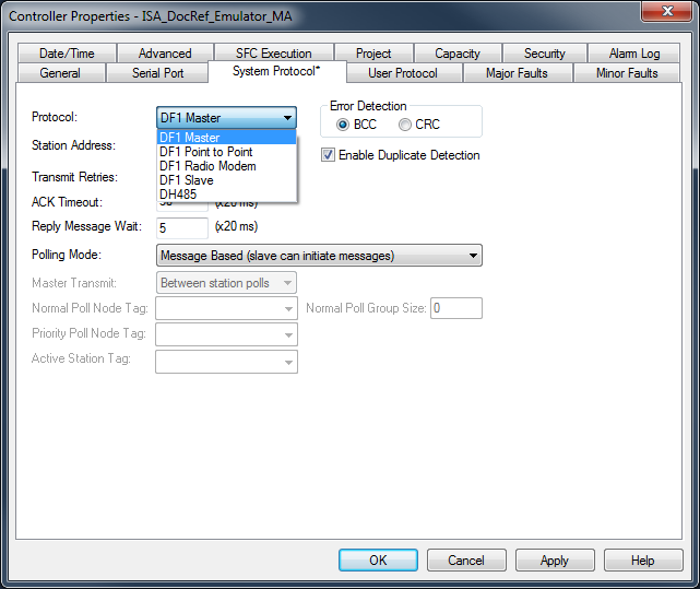
button and select a channel to default a path for the message.- On theController Organizer, right-clickController, and selectProperties. TheController Propertiesdialog box appears.
- Click theSystem Protocoltab.
- SelectDF1 Masterin theProtocolbox. The Polling mode defaults ‘Message Based’ (slave can initiate messages).
- ClickOK.
- In ladder logic, click the box inside the MSG tag. TheMessage Configurationdialog box appears with theConfigurationtab open.
- In theMessage Typebox, selectCIP Data Table Write.
- ClickOK.You have enabled theBroadcastbutton on theCommunicationtab.
- Click theCommunicationtab.
- Next to theBroadcastbutton, select a channel in the combo box. The number of channels in the combo box depends on the controller.When you select channel 0 or 1, the corresponding message path on theMessage Configurationdialog box defaults to 2,255 (channel 0) or 3,255 (channel 1). The Path grays out to not allow you to manually enter a path value.
- ClickOK.
System Protocol Tab Configuration
NOTE:
Logix Designer versions 37 and later do not support controllers with serial ports. The
System Protocol
tab appears only in Logix Designer versions 36 and earlier for controllers with a serial port.To run broadcast in
ControlLogix
controllers in the Logix Designer application, you must configure the System Protocol
tab in the Controller Properties
dialog box. The protocol must be compatible with the message type of ‘write’ on the Message Configuration
dialog box.Follow these steps to set up the system protocol to be compatible with the broadcast feature.
- Create or open an existing controller in the application.
- On theController Organizer, right-click the controller name, and selectProperties.TheController Propertiesdialog box appears.
- If you controller has a serial port, clickSystem Protocoltab.
- In the Protocol box, select a protocol.IMPORTANT:TheMessage Typebox on theMessage Configuration Tabdialog box must be write-typed to be compatible with the system protocol. Otherwise, theBroadcastbutton is disabled.
- Enter the information on theSystem Protocoltab for each protocol outlined in the following tables.TopicDescriptionProtocolDF-1 MasterStation AddressType controller station address numberTransmit Retries3ACK Timeout50Reply Message Wait5Polling ModeSelect from the following modes:
- Message BasedPoll the slave using message instruction
- Slave can initiate messagefor slave to slave broadcast
- Standard. to have the schedule poll for the slave
Error DetectionBCCDuplicate DetectionEnabled (checked)TopicDescriptionProtocolDF-1 SlaveStation AddressType controller station address numberTransmit Retries3Slave Poll Timeout3000EOT SuppressionDisable (unchecked)Error DetectionBCCDuplicate DetectionEnabled (checked)TopicDescriptionProtocolDF-1 SlaveStation AddressType controller station address numberEnable Store and ForwardEnable box (checkmark) to use store and forward tagError DetectionBCC - ClickOK.
For Block Transfers
For block transfer messages, add the following modules to the I/O configuration of the controller:
For block-transfers over this network: | Add these modules to the I/O configuration: |
|---|---|
ControlNet | Local communication module (for example, 1756-CNB module) Remote adapter module (for example, 1771-ACN module) |
Universal remote I/O | Local communication module (for example, 1756-DHRIO module) One remote adapter module (for example, 1771-ASB module) for each rack, or portion of a rack, in the chassis Block-transfer module (optional) |
Specify a Communication Method or Module Address
Use the following table to select a communication method or module address for the message:
If the destination device is | Select | And specify | |
|---|---|---|---|
Logix 5000 controller | CIP | No other specifications required. | |
PLC-5 controller over an EtherNet/IP network | |||
PLC-5 controller over a ControlNet network | |||
SLC 5/05 controller | |||
PLC-5 controller over a DH+ network | DH+ | Channel | Channel A or B of the 1756-DHRIO module that is connected to the DH+ network. |
SLC controller over a DH+ network | Source Link | Link ID assigned to the backplane of the controller in the routing table of the 1756-DHRIO module. The source node in the routing table is automatically the slot number of the controller. | |
PLC-3 processor | Destination Link | Link ID of the remote DH+ link where the target device resides. | |
PLC-2 processor | Destination Node | Station address of the target device, in octal. | |
If there is only one DH+ link and you did not use the RSLinx Classic software to configure the DH/RIO module for remote links, specify 0 for both the Source Link and the Destination Link. | |||
Application on a workstation that is receiving an unsolicited message routed over an EtherNet/IP or ControlNet network through RSLinx Classic or FactoryTalk Linx software | CIP with Source ID This lets the application receive data from a controller. | Source Link | Remote ID of the topic in RSLinx Classic software, or the shortcut in FactoryTalk Linx . |
Destination Link | Virtual Link ID set up in RSLinx Classic or FactoryTalk Linx software (0…65535). | ||
Destination Node | Destination ID (0…77 octal) provided by the application to RSLinx Classic or FactoryTalk Linx . For a DDE topic in RSLinx Classic , use 77. | ||
The slot number of the ControlLogix controller is used as the Source Node. | |||
Block transfer module over a universal remote I/O network | RIO | Channel | Channel A or B of the 1756-DHRIO module that is connected to the RIO network. |
Rack | Rack number (octal) of the module. | ||
Group | Group number of the module. | ||
Slot | Slot number of the module. | ||
Block transfer module over a ControlNet network | ControlNet | Slot | Slot number of the module. |
Choose a Cache Option
Depending on the configuration of an MSG instruction, it may use a connection to send or receive data.
Message type: | Communication method: | Uses a connection: |
|---|---|---|
CIP data table read or write | Your option(1) | |
PLC-2, PLC-3, PLC-5, or SLC (all types) | CIP CIP with Source ID | |
DH+ | X | |
CIP generic | Your option(2) | |
Block-transfer read or write | X |
- CIP data table read or write messages can be connected or unconnected. For most applications,Rockwell Automationrecommends that you leave CIP data table read or write messages connected.
- CIP generic messages can be connected or unconnected. But, for most applications, we recommend you leave CIP generic messages unconnected.
If a MSG instruction uses a connection, you have the option to leave the connection open (cache) or close the connection when the message is done transmitting.
If you: | Then: |
|---|---|
Cache the connection | The connection stays open after the MSG instruction is done. This optimizes execution time. Opening a connection each time the message executes increases execution time. |
Do not cache the connection | The connection closes after the MSG instruction is done. This frees up that connection for other uses. |
The controller has the following limits on the number of connections that you can cache.
If you have this controller: | Then you can cache: |
|---|---|
CompactLogix 5370 or ControlLogix 5570 | Up to 32 connections. |
ControlLogix 5580 | Up to 256 connections. |
If several messages go to the same device, the messages may be able to share a connection.
If the MSG instructions are to: | And they are: | Then: |
|---|---|---|
Different devices | Each MSG instruction uses 1 connection. | |
Same device | Enabled at the same time | Each MSG instruction uses 1 connection. |
NOT enabled at the same time | The MSG instruction uses 1 connection and 1 cached buffer. They share the connection and the buffer. |
TIP:
To share a connection, if the controller alternates between sending a block-transfer read message and a block-transfer write message to the same module, both messages count as one connection. Caching both messages counts as one on the cache list.
Guidelines
As you plan and program your MSG instructions, follow these guidelines:
Guideline | Details |
|---|---|
For each MSG instruction, create a control tag. | Each MSG instruction requires its own control tag. |
Data type = MESSAGE | |
Scope = controller | |
The tag cannot be part of an array or a user-defined data type. | |
Keep the source and/or destination data at the controller scope. | A MSG instruction can access only tags that are in the Controller Tags folder (controller scope). |
If your MSG is to a device that uses 16-bit integers, use a buffer of INTs in the MSG and DINTs throughout the project. | If your message is to a device that uses 16-bit integers, such as a PLC-5 or SLC 500 controller, and it transfers integers (not REALs), use a buffer of INTs in the message and DINTs throughout the project. |
This increases the efficiency of your project because Logix controllers execute more efficiently and use less memory when working with 32-bit integers (DINTs). | |
To convert between INTs and DINTs, see the Logix 5000 Controllers Common Procedures Programming Manual, publication 1756-PM001. | |
Cache the connected MSGs that execute most frequently. | Cache the connection for those MSG instructions that execute most frequently, up to the maximum number permissible for your controller revision. This optimizes execution time because the controller does not have to open a connection each time the message executes. |
For the CompactLogix 5370 or ControlLogix 5570 controllers , if you want to enable more than 16 MSGs at one time, use some type of management strategy.
For the ControlLogix 5580 controllers, if you want to enable more than 256 MSGs at one time, use some type of management strategy. | For the CompactLogix 5370 or ControlLogix 5570 controllers, if you enable more than 16 MSGs at one time, some MSG instructions may experience delays in entering the queue. For the ControlLogix 5580 controllers, if you enable more than 256 MSGs at one time, some MSG instructions may experience delays in entering the queue. To help make sure that each message executes, use one of these options: |
Enable each message in sequence. | |
Enable the messages in groups. | |
Program a message to communicate with multiple devices. For more information, see the Logix 5000 Controllers Common Procedures Programming Manual, publication 1756-PM001. | |
Program logic to coordinate the execution of messages. For more information, see the Logix 5000 Controllers Common Procedures Programming Manual, publication 1756-PM001. | |
(For the CompactLogix 5370 or ControlLogix 5570 controllers only) Keep the number of unconnected and uncached MSGs less than the number of unconnected buffers. | The controller can have 10…40 unconnected buffers. The default number is 10 for the CompactLogix 5370 or ControlLogix 5570 controllers. |
If all the unconnected buffers are in use when an instruction leaves the message queue, the instruction errors and does not transfer the data. | |
You can increase the number of unconnected buffers (40 max), but continue to follow guideline 5. | |
To increase the number of unconnected buffers, see the Logix 5000 Controllers Common Procedures Programming Manual, publication 1756-PM001. |
Provide Feedback