- Studio 5000 Logix Designer
- Tasks, programs, and routines
- Add-On Instructions
- Controller Organizer
- Logical Organizer
- Alarms
- Tag-based alarms
- Tag Editor and Data Monitor
- Configure settings for Tag Editor and Data Monitor
- Equipment phases
- Equipment Sequences
- Equipment Sequence Diagrams
- Ladder Editor
- Structured Text Editor
- Sequential Function Chart Editor
- Define the steps of an SFC process
- PlantPAx instruction properties
- Controller Properties
- Editing Controller Properties
- Controller Security
- Source Protection
- License Source Protection for Routines and Add-On Instructions
- Module Information
- 1756 ControlLogix I/O Modules
- Instruction Set
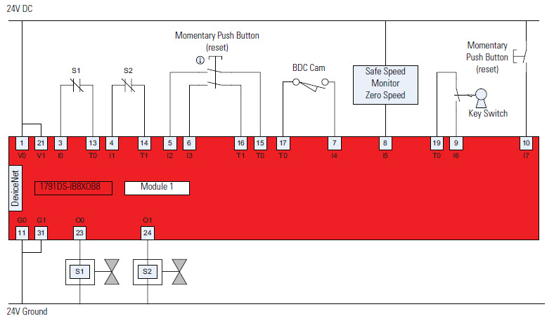
MMVC wiring and programming example
This topic demonstrates how to wire the Guard I/O module and program the instruction in the safety control portion of an application.
This application example complies with ISO 13849-1, Category 4 operation.
TIP:
The standard control portion of the application is not shown in the following diagram.
Wiring Diagram
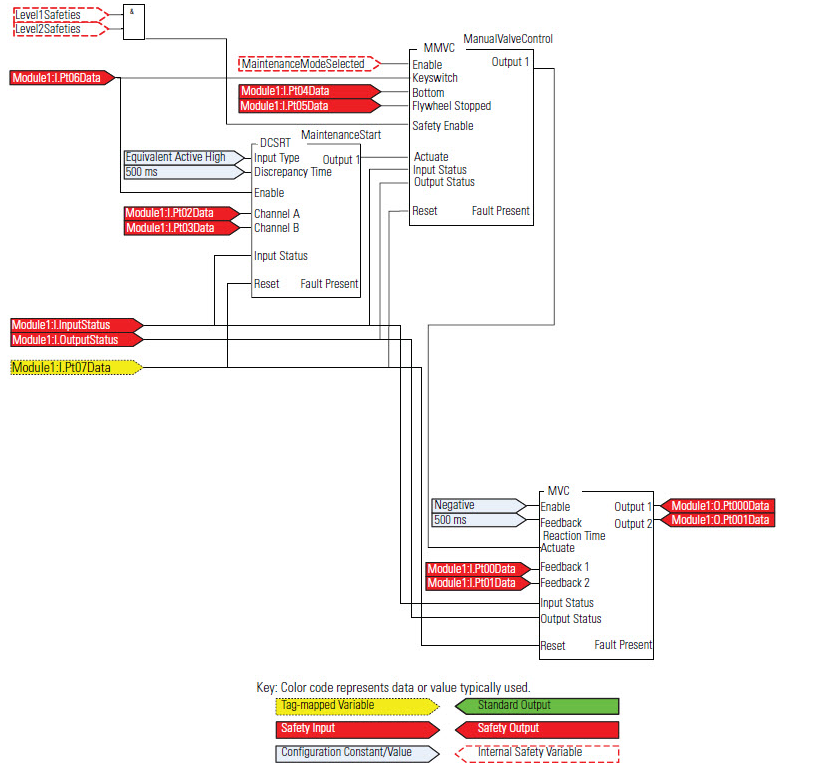
This programming diagram shows the MMVC instruction used with a Dual-channel Input Start (DCSRT) instruction and a Main Valve Control (MVC) instruction.
Programming Diagram
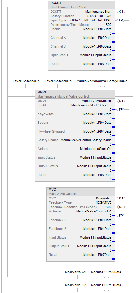
Ladder Diagram
Module Definition
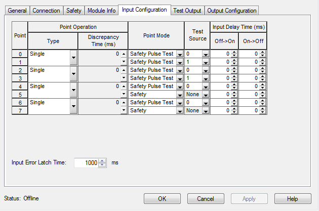
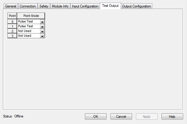
The Logix Designer application is used to configure the input and test output operands of the Guard I/O module, as illustrated.
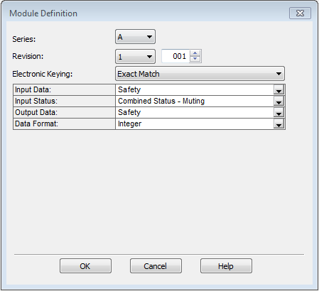
Rockwell Automation suggests selecting
Exact Match
for the Electronic Keying
as shown. Compatible Match
is also acceptable.Module Input Configuration
Module Test Output Configuration
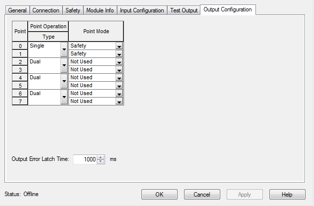
Module Output Configuration
Provide Feedback