- Studio 5000 Logix Designer
- Tasks, programs, and routines
- Add-On Instructions
- Controller Organizer
- Logical Organizer
- Alarms
- Tag-based alarms
- Tag Editor and Data Monitor
- Configure settings for Tag Editor and Data Monitor
- Equipment phases
- Equipment Sequences
- Equipment Sequence Diagrams
- Ladder Editor
- Structured Text Editor
- Sequential Function Chart Editor
- Define the steps of an SFC process
- PlantPAx instruction properties
- Controller Properties
- Editing Controller Properties
- Controller Security
- Source Protection
- License Source Protection for Routines and Add-On Instructions
- Module Information
- 1756 ControlLogix I/O Modules
- Instruction Set
Motion Error Codes .ERR
This table lists the error codes for
Logix Designer
software motion instructions.Motion Instruction Error Codes Descriptions
Error | Corrective Action or Cause | Notes |
1 | Reserved Error Code 1 | Reserved for future use. |
2 | Reserved Error Code 2 | Reserved for future use. |
3 | Look for another instance of this type of instruction. See if its EN bit is on but its DN and ER bits are off (enabled but not done or erred). Wait until its DN or ER bit turns on. | Execution Collision You cannot execute an instruction by using the same control word as another instruction if the other instruction is not done or has an error. Regardless, it is recommended that each instruction has a unique control word. |
4 | Open the servo loop before you execute this instruction. | Servo On State Error |
5 | Close the servo loop before you execute this instruction. | Servo Off State Error For a motion coordinated instruction, refer to the online help for the instruction for extended error code definitions. They identify which axis caused the error. Example: If the extended error code is zero, check the axis for index zero of the coordinate system. |
6 | Disable the axis drive. | Drive On State Error |
7 | Execute a Motion Axis Shutdown Reset (MASR) instruction or direct command to reset the axis. | Shutdown State Error For a motion coordinated instruction, refer to the online help for the instruction for extended error code definitions. They identify which axis caused the error. Example: If the extended error code is zero, check the axis for index zero of the coordinate system. |
8 | The configured axis type is not correct. | Wrong Axis Type For a motion coordinated instruction, refer to the online help for the instruction for extended error code definitions. They identify which axis caused the error. Example: If the extended error code is zero, check the axis for index zero of the coordinate system. |
9 | The instruction tried to execute in a direction that aggravates the current overtravel condition. | Overtravel Condition |
10 | The master axis reference is the same as the slave axis reference or the Master Axis is also an axis in the Save Coordinate System. | Master Axis Conflict |
11 | At least one axis is not configured to a physical motion module or has not been assigned to a Motion Group. | Axis Not Configured For single axis instructions: the Extended Error code for MAG, MDAC, MAPC, MAM, MAJ, MATC, and MCD is defined as: 1 = Slave axis 2 = Master Axis For the MAM, MCD, and MAJ instructions in time driven mode, the axis being moved is a slave axis. For multi-axes instructions: the Extended Error code for MDCC, MCLM, MCCM, MCCD, and MCPM is defined as: The axis number in the coordinate system where 0 = 1st axis 2 = Master Axis or 3rd Slave Axis |
12 | Messaging to the servo module failed. | Servo Message Failure |
13 | Refer to the online help for the instruction for extended error code definitions. Example: An MAJ instruction has an ERR = 13 and an EXERR = 3. In this case, change the speed so that it’s in range. 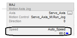 | Parameter Out Of Range An EXERR = 0 means the first operand of the instruction is outside its range. |
14 | The instruction cannot apply the tuning parameters because of an error in the run tuning instruction. | Tune Process Error |
15 | The instruction cannot apply the diagnostic parameters because of an error in the run diagnostic test instruction. | Test Process Error |
16 | Wait until the homing process is done. For coordinated move instructions, it identifies which axis caused the error. | Home In Process Error |
17 | The instruction tried to execute a rotary move on an axis that is not configured for rotary operation. | Axis Mode Not Rotary |
18 | The axis type is configured as unused. | Axis Type Unused |
19 | The motion group is not in the synchronized state. This could be caused by a missing or misconfigured servo module. | Group Not Synchronized Group sync status is only cleared on a group overlap or CST loss fault. |
20 | The axis is in the faulted state. | Axis In Faulted State |
21 | The group is in the faulted state. | Group In Faulted State |
22 | Stop the axis before you execute this instruction. | Axis In Motion |
23 | An instruction attempted an illegal change of dynamics. | Illegal Dynamic Change |
24 | Take the controller out of test mode. | Illegal Controller Mode |
25 | Either one of these could be the reason for the error:
| Illegal Instruction |
26 | The cam array is of an illegal length. | Illegal Cam Length |
27 | The cam profile array is of an illegal length. | Illegal Cam Profile Length |
28 | You have an illegal segment type in the cam element. | Illegal Cam Type The .SEGMENT field of Motion Instruction identifies which cam profile element contains the invalid segment type. A .SEGMENT = 3 means the 4th element (or [3]) of the cam profile array contains the invalid segment type. |
29 | You have an illegal order of cam elements. | Illegal Cam Order The .SEGMENT field of Motion Instruction identifies which cam profile element contains the invalid (non-ascending) master value. A .SEGMENT = 3 means the 4th element (or [3]) of the cam profile array contains the invalid (non-ascending) master value. |
30 | You tried to execute a cam profile while it is being calculated. | Cam Profile Being Calculated |
31 | The cam profile array you tried to execute is in use. | Cam Profile Being Used |
32 | The cam profile array you tried to execute has not been calculated. | Cam Profile Not Calculated |
33 | A MAM - Master Offset move was attempted without a Position CAM in process. | Position Cam Not Enabled |
34 | A MAH instruction is trying to start while a registration is already running. | Registration in Progress |
35 | The specified execution target exceeds the number of Output Cam targets configured for the axis. | Illegal Execution Target |
36 | Either the size of the Output Cam array is not supported or the value of one of its members is out of range. | Illegal Output Cam ExErr#1: Output bit less than 0 or greater than 31. ExErr#2: Latch type less than 0 or greater than 3. ExErr#3: Unlatch type less than 0 or greater than 5. ExErr#4: Left or right position is out of cam range and the latch or unlatch type is set to `Position’ or `Position and Enable’. ExErr#5: Duration less than or equal to 0 and the unlatch type is set to `Duration’ or `Duration and Enable’. ExErr#6: Enable type less than 0 or greater than 3 and the latch or unlatch type is set to `Enable’, `Position and Enable’, or `Duration and Enable’. ExErr#7: Enable bit less than 0 or greater than 31 and the latch or unlatch type is set to `Enable’, `Position and Enable’, or `Duration and Enable’. ExErr#8: Latch type is set to `Inactive’ and unlatch type is set to either `Duration’ or `Duration and Enable’. |
37 | Either the size of the Output Compensation array is not supported or the value of one of its members is out of range. The array index associated with errors 36 and 37 are stored in .SEGMENT of the Motion Instruction data type. Only the first of multiple errors are stored. The specific error detected is stored in Extended Error Code. With the ability to dynamically modify the Output Cam table, the Illegal Output Cam error 36 can occur while the MAOC is in-process. In general, the cam elements where an error was detected will be skipped. The following are exceptions and will continue to be processed. Error 2, Latch Type Invalid. Latch Type defaults to Inactive. Error 3, Unlatch Type Invalid. Unlatch Type defaults to Inactive. Error 8, with Unlatch Type of Duration and Enable. Will behave as an Enable Unlatch type. | Illegal Output Compensation ExErr#1: Mode less than 0 or greater than 3. ExErr#2: Cycle time less than or equal to 0 and the mode is set to `Pulsed’ or `Inverted and Pulsed’. ExErr#3: Duty cycle less than 0 or greater than 100 and the mode is set to `Pulsed’ or `Inverted and Pulsed’. |
38 | The axis data type is illegal. It is incorrect for the operation. | Illegal Axis Data Type |
39 | You have a conflict in your process. Test and Tune cannot be run at the same time. | Process Conflict |
40 | You are trying to run a MSO or MAH instruction when the drive is locally disabled. | Drive Locally Disabled |
41 | The Homing configuration is illegal. You have an absolute homing instruction when the Homing sequence is not immediate. | Illegal Homing Configuration |
42 | The MASD or MGSD instruction has timed out because it did not receive the shutdown status bit. Usually a programmatic problem caused when either MASD or MGSD is followed by a reset instruction that is initiated before the shutdown bit has been received by the shutdown instruction. | Shutdown Status Timeout |
43 | You have tried to activate more motion instructions than the instruction queue can hold. | Coordinate System Queue Full |
44 | You have drawn a line with three 3 points and no centerpoint viapoint or plane centerpoint can be determined. | Circular Collinearity Error |
45 | You have specified one 1 point radius or "drawn a line" centerpoint, viapoint and no centerpoint radius or plane centerpoint, viapoint can be determined. | Circular Start End Error |
46 | The programmed centerpoint is not equidistant from start and end point. | Circular R1 R2 Mismatch Error |
47 | Contact Rockwell Automation Support. | Circular Infinite Solution Error |
48 | Contact Rockwell Automation Support. | Circular No Solutions Error |
49 | |R| < 0.01. R is basically too small to be used in computations. | Circular Small R Error |
50 | The coordinate system tag is not associated with a motion group. | Coordinate System Not in Group |
51 | You have set your Termination Type to Actual Position with a value of 0. This value is not supported. | Invalid Actual Tolerance |
52 | At least one axis is currently undergoing coordinated motion in another coordinate system. | Coordination Motion In Process Error |
53 | Uninhibit the axis. | Axis Is Inhibited For single axis instructions, the Extended Error code for MAG, MDAC, MAPC, MAM, MAJ, MATC, and MCD is defined as: 1 = Slave axis 2 = Master Axis For the MAM, MCD, and MAJ instructions in time driven mode, the axis being moved is a slave axis. For multi-axes instructions, the Extended Error code for MDCC, MCLM, MCCM, MCCD, MCTO, and MCPM is defined as: The axis number in the coordinate system where 0 = 1st axis 2 = Master Axis or 3rd Slave Axis |
54 | You cannot start motion if the maximum deceleration for the axis is zero. For coordinated move instructions, it identifies which axis caused the error. | Zero Max Decel |
61 | Refer to the online help for the instruction for extended error code definitions. | Connection Conflict |
62 | Cancel the transform that controls this axis or don’t use this instruction while the transform is active. | Transform In Progress You cannot execute this instruction if the axis is part of an active transform. |
63 | Cancel the transform that controls this axis or wait until the transform is done moving the axis. | Axis In Transform Motion You cannot execute this instruction if a transform is moving the axis. |
64 | Use a Cartesian coordinate system. | Ancillary Not Supported You cannot use a non-Cartesian coordinate system with this instruction. |
65 | Once the error occurs, position the axis (or master axis) within bounds to execute instructions generating motion on the axis. This error occurs with MAM, MAPC, MCLM, MCCM, MCPM instructions and axes that are part of Kinematics transforms. This error occurs when instruction executes and the absolute position is outside the overtravel limits. | Absolute position outside the overtravel limits |
66 | Be sure to keep the robot in the arm solution that you configured it in. You can configure the robot in either a left arm or right arm solution. | You are attempting to fold back an articulated independent or dependent two axis robot on itself at the quadrant boundaries. |
67 | Either one of these could be the reason for the error: 1. You’re trying to move to a place the robot cannot reach. 2. MCT, MCTO, MCTP or MCTPO attempted while at origin. To avoid having the robot fold back on itself or extend beyond its reach, joint limits are calculated internally by the firmware for Delta2D, Delta3D and SCARA Delta robots. If you try and configure a move that violates these limits, this error occurs. Refer to the online help for the instruction for extended error code definitions. It identifies which orientation axis caused the error. | Invalid Transform Position |
68 | Move the joints so that the end of the robot is not at the origin of the coordinate system. | Transform At Origin You cannot start the transform if the joint angles result in X1 = 0 and X2 = 0. |
69 | Check the maximum speed configuration of the joints. Use target positions that keep the robot from getting fully stretched or folding back on itself at the origin of the coordinate system. Move in a relatively straight line through positions where X1 = 0 and X2 = 0. | Max Joint Velocity Exceeded The calculated speed is very high. This happens when the robot either: gets fully stretched. folds back on itself. moves away from X1 = 0 and X2 = 0 in a different angle than it approached that position. is configured with the wrong velocity limit. Example: These moves produce this error. 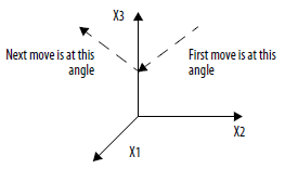 |
70 | Look for source or target axes that are configured as rotary positioning mode. Change them to linear positioning mode. | Axes In Transform Must Be Linear A transform works only with linear axes. |
71 | Wait until the transform that you are canceling is completely canceled. | Transform Is Canceling |
72 | Check the target positions. A calculated joint angle is beyond +/- 360⋅. | Max Joint Angle Exceeded |
73 | Check that each MCT instruction in this chain is producing valid positions. | Coordinate System Chaining Error This MCT instruction is part of a chain of MCT instructions. There is a problem with one of the instructions in the chain. |
74 | Change the orientation to angles that are within +/- 360⋅. | Invalid Orientation Angle |
75 | Use this instruction only with a 1756-L6x controller. | Instruction Not Supported You can use an MCT or MCTP instruction only with a 1756-L6x controller. |
76 | You cannot start motion that uses an S-curve profile if the maximum deceleration jerk for the axis is zero. 1. Open the properties for the axis. 2. On the Planner tab, enter a value for the Maximum Deceleration Jerk . | Zero Max Decel Jerk |
77 | How many axes are in your coordinate system? 2 — Use a non-mirror transform direction. 3 — Use a non-inverse transform direction. | Transform Direction Not Supported You're trying to use the mirror directions with a 3-axis coordinate system and a non-zero base offset (X2b) or effector offset (X2e). Mirror directions are not supported for 2-axis Coordinate Systems. You are attempting to use either a 2 or 3-axis Cartesian, Delta2D, Delta3D or SCARA Delta target coordinate system with transform directions other than forward and inverse. You can use inverse mirror directions only when both these conditions are true: You have a 3-axis coordinate system. The base offset (X2b) and end effector offset (X2e) of the X2 dimension are zero. |
78 | New check for a secondary Instruction overlap on top of an active Stop instruction. | Not Allowed While Stopping You cannot overlap certain Motion instructions while stopping. Wait for the first instruction to complete before starting the second instruction. |
79 | Home your axis again. Error of Home instruction occurs, if any other motion on the axis is encountered during the homing sequence. | Internal Homing Sequence Error Invalid Planner State If you see this error, rehome your axis in your application program. Make sure the axis is stopped before home is attempted. If the error persists, contact Rockwell Automation Support. |
80 | When referencing a Scheduled Output Module, for example, the OB16IS, make sure that the Output operand of the MAOC references O:Data, and that the Scheduled Output Module's communication format is set to `Scheduled Output Data per point’. | MAOC Invalid Output Operand If the MAOC output operand references an OB16IS Scheduled Output module, two additional checks occur when the MAOC is initiated. The Output operand must be referencing the beginning of the module’s output data tag, 'O.Data'. The communications format of the OB16IS module must be the default "Scheduled Output Data per Point". If either of these checks fail you see this error. ExErr#1: Invalid Data Tag Reference - The Output operand is not pointing to the O.Data element of the module’s output data tag. This is applicable to 5069-OB16F, 1756-OB16IEFS, 1732E-OB8M8SR, and OB16IS modules only. ExErr#2: Invalid Module Communication Format for one of these modules: 5069-OB16F, 1756-OB16IEFS, 1756-OB16IS, 1732E-OB8M8SR modules. ExErr#3: CIP Sync not synchronized - Scheduled output module reporting not synchronized to a CIP Sync master. Applicable to the 5069-OB16F, 1756-OB16IEFS, 1732E-OB8M8SR modules only. ExErr#4: Grandmaster Clock mismatch - Scheduled output module has different Grandmaster clock than the controller. Applicable to the 5069-OB16F, 1756-OB16IEFS, 1732E-OB8M8SR modules only. |
81 | Error on MGSR, if a MASD or MGS (programmed) is executed while the MGSR is still in process. Do not overlap the MASD instruction or MGS stop instruction with Stop Mode = Programmed on an active MGSR instruction. | Partial Group Shutdown Reset. If your application program is actively executing an MGSR instruction and you try to execute an MASD instruction or MGS stop instruction with Stop Mode = Programmed on one of the axes affected by the active MGSR instruction, you will see this error on the MGSR instruction. |
82 | The axis was found to be in the incorrect operational axis state. | CIP axis in incorrect state. |
83 | This instruction cannot be performed due to control mode or feedback selection. | Illegal Control Mode or Method. The MDS instruction is not valid in Position Loop or Feedback Only modes. The error also triggers when the CIP motion device does not have a valid feedback to perform the instruction. |
84 | The CIP drive device digital input is not assigned. | Drive Digital Input Not Assigned |
85 | Instruction not allowed when redefine position is in process. Performing MAH while MRP is in process results in this instruction error. | Homing, redefine position in progress An Active Redefine Position instruction is in process. You would get this error if any of the motion planner instructions are executed while MRP is in progress. Motion Instructions included are: MAM, MAJ, MCLM , MCCM, MATC, MAPC , MDAC, MDCC, and MCPM. |
86 | Current use of the MDS instruction requires an optional attribute that is not supported. | Optional attribute not supported by the integrated motion drive being used. Executing a MDS instruction on a CIP- Velocity Loop with Feedback axis associated with a Kinetix 6500 drive errors. The instruction requires an optional attribute that is not currently supported.The MDS instruction is not supported by the drive type. |
87 | The instruction is invalid while running direct controlled motion. | Not Allowed While In Direct Motion |
88 | The instruction is invalid while running planned motion. | Not Allowed While Planner Active |
93 | A move was programmed in MDSC mode before the MDSC link has been established by the execution of a MDAC or MDCC. | MDSC Not Activated |
94 | Some dynamics units belong to Master Driven Mode and some to Time Driven Mode. Some units are time based whereas others are velocity based, for example, Speed in Seconds and Acceleration in units/sec2. Incompatibility of units. Dynamics in Seconds are incompatible with Merge Speed = Current. | MDSC Units Conflict |
95 | All instructions in the queue must use a compatible Lock Direction, for example, Position Forward Only and Immediate Forward Only. Lock Direction = None and speed units belong to Master Driven Mode. | MDSC Lock Direction Conflict If you change from Time Driven mode to Master Driven mode while an axis is moving and Lock Direction is not Immediate Forward or Reverse you will get error 95 MDSC Lock Direction Conflict. |
96 | MDAC (All) and MDAC (something other than All) on the same slave. | MDSC MDAC All Conflict |
97 | Trying to replace a running Master with a new Master whose speed is zero, or replacing a Slave that is moving via an MAM with another MAM with the same or a different Master that is not moving. | MDSC Idle Master and Slave Moving |
98 | The actual direction of master axis’ motion does not match the direction programmed by Lock Direction parameter (IMMEDIATE FORWARD ONLY or IMMEDIATE REVERSE ONLY) when the slave is already moving. | MDSC Lock Direction Master Direction Mismatch |
99 | Either of these could be the reason for the error:
| MDSC Feature Not Supported |
100 | If speed is in seconds or Master units, move must start from rest. | Axis Not At Rest. |
101 | Return data array is either nonexistent or not big enough to store all the requested data. | MDSC Calculated Data Size Error. |
102 | Attempt to activate a second MDSC instruction with a Lock Position or a Merge with a Lock Position while an axis is moving. | MDSC Lock While Moving. |
103 | If the Master Axis is changed and the new slave speed is less than 5% of the original slave speed for Single Axis instructions, or 10%, depending on the move of the original Slave Coordinate System speed, then this error will occur and the change will not be allowed. The same applies when changing from Time Driven mode to MDSC mode. | MDSC Invalid Slave Speed Reduction. |
104 | IF: a motion instruction performs either: A change in the Master Axis A change in speed units AND: if in the same update period, the instruction is either forced to pause with a speed of zero, or stopped with a MAS or MCS THEN: the velocity profile is changed to trapezoidal and this error code is reported. | MDSC 2 Instructions were started in 1 Update Period therefore Jerk was Maximized. |
105 | An instruction in the coordinated motion queue is either trying to change the Master Axis or changing the mode from MDSC mode to Time Driven mode or from Time Driven mode to MDSC mode. | MDSC Invalid Mode Or Master Change. |
106 | Cannot use Merge to Current when programming in time driven mode using seconds or master driven mode using master units. Change merge speed parameter. | Merge to Current using seconds is illegal. |
107 | Target device does not support the requested operation, service, or both. | There is not any corrective action that can be taken. |
108 | Coordinated System contains a multiplexed axis. | Motion coordinated instructions cannot contain multiplexed axes. |
109 | You attempted to use an axis that is defined as a converter or track section. | Invalid Axis Configuration A converter or track section cannot be used for this instruction. |
110 | You attempted to put an axis configured as a converter into a coordinate system definition. | A converter cannot be used for this instruction. |
111 | You cannot start motion if the maximum acceleration for the axis is zero.
| Zero Max Accel |
112 | Operand Nominal Master Velocity in MDCC instruction must be equal to zero in
CompactLogix 5370, ControlLogix 5570, Compact GuardLogix 5370, and GuardLogix 5570 controllers | Operand not supported. |
121 | The Coordinate Definition cannot be set to <none>. | Invalid coordinate definition for the instruction. |
125 | Operand 0 must be a Cartesian coordinate system type. | Source coordinate system is not Cartesian. |
126 | Operand 1 must NOT be a Cartesian coordinate system type. | Target coordinate system is Cartesian. |
128 | Turns counter functionality is not supported. Turns counter is not supported on J1 and J4 on 4 axis geometries and J1 and J6 on 5 axis geometries. Turns counter functionality is not supported when transform is disabled. | Turns Counter Not Supported.
|
130 | Cannot use the Coordinate system that supports orientation with MCLM, MCCM and MCCD instructions. Corrective action: 1. Modify the coordinate definition of the Cartesian coordinate system to <none> OR 2. Use the configured Cartesian Coordinate system XYZRxRyRz with the MCPM instruction which supports orientation axes control. | Not allowed on the orientation supported geometries. |
132 | Operands of MCS should be set as follows. Otherwise the instruction will error. 1. If Change Decel is set to Yes , then Decel Units must be % of Maximum . Units per Sec2 is not acceptable because different decel value is needed for Cartesian and orientation axes.2. Change Decel Jerk must be set to Yes . Setting it to No is not acceptable because different jerk value is needed for Cartesian and orientation axes.3. Decel Jerk Units must be programmed in % of time . Units per Sec3 and % of Maximum, are not acceptable because different value is needed for Cartesian and orientation axes. | MCS Units conflict. |
135 | If MCPM speed, accel or decel units are programmed in % of max and the associated master driven MDCC instruction nominal master velocity is set to zero, the instruction will error. | MCPM zero nominal master velocity. |
136 | There are two possible situations that can result in this conflict:
| MCPM robot configuration conflict. |
137 | The robot configuration parameter for the MCTPO instruction is not valid for this Robot geometry. | Invalid robot configuration. |
138 | Refer to the extended error codes in the online help for the MCPM instruction for details related to this error code. | MCPM path data invalid value. |
139 | Refer to the extended error codes in the online help for the MCPM instruction for details related to this error code. | MCPM Dynamics Data invalid value. |
140 | Wait until the Servo On operation is complete. | Servo On in progress. |
141 | Wait until the Servo Off operation is complete. | Servo Off in progress. |
142 | Wait for the Shutdown Reset operation to complete. | Shutdown Reset in progress. |
143 | Wait for Axis Homing to complete. | Home in progress. |
144 | Wait for the Motion redefine position operation to complete. | Redefine in progress. |
145 | Wait for the Shutdown operation to complete. | Shutdown in progress. |
146 | Cannot start motion if the maximum orientation deceleration for the coordinate system is zero. | Maximum orientation deceleration is zero. |
147 | A orientation axis (Rx, Ry, or Rz) in the coordinate system has one of the following:
Refer to the online help for the instruction for extended error code definitions. It identifies the orientation axis. | Invalid orientation scaling constant. |
148 | The MCTO or MCTPO instruction reports this error when the Orientation offset is not valid when:
Refer to the online help for the instruction for extended error code definitions. It identifies the orientation axis. | MCTO or MCTPO orientation offset is not zero. |
149 | Orientation axes (Rx, Ry, and Rz) must be virtual if the coordinate system is involved in the MCTO or MCTPO transforms. Refer to the online help for the instruction for extended error code definitions. It identifies the orientation axis. | Orientation axis is not virtual. |
150 | The instruction reports this error when an orientation axis (Rx, Ry, or Rz) is used as a master axis of a gearing, camming, or master driven instructions | Master axis is orientation axis. |
151 | The Joint angle in a Delta J1JJ2J6, DeltaJ1J2J3J6, or Delta J1J2J3J4J5 geometry goes beyond the joint angle limit. Refer to the online help for the instruction for extended error code definitions. It identifies the Joint that is outside its range. | Joint angle beyond its limits. |
152 | Error occurs when the orientation axis is commanded to move by and angle greater than or equal to 180 degrees in one coarse update period. Refer to the online help for the instruction for extended error code definitions. It identifies the orientation axis. | Maximum orientation speed exceeded for an orientation axis. |
153 | The error occurs if the programmed Cartesian position (X, Y or Z) cannot be attained by the robot. For example: A Delta J1J2J6 robot can operate only in a 2D X-Z plane without a tool. If you program a Cartesian point with Y, a non-zero value, this error occurs with extended error 2 that represents invalid translation position Y. Refer to the online help for the instruction for extended error code definitions. It identifies the Joint that is outside its range. | Invalid translation position. |
155 | MCPM currently does not support any action on 6-axis robot geometry, so if attempted this error occurs. | Robot geometry is not supported in MCPM. |
170 | The instruction reports this error when a cam replacement is attempted when there is no active cam. | |
171 | The error occurs when attempting to replace a cam and replacement point not in range of cam profile. | |
172 | Attempting to replace a cam when Execution Schedule is “Pending”. | The cam type is “Replace and Restart” or “Replace and continue” and the Execution Schedule is “Pending”. Execution Schedule of “Pending” is only associated with cam type “New Cam”. |
173 | Cam completed before crossing the replacement position. | 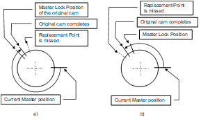 |
174 | The start point for cam replacement is beyond existing cam boundary. |  Example: An Active cam is locked, and Master Lock Position of a replacement cam is set to a point beyond the right cam boundary. |
176 | Motion Calculate Slave Values (MCSV) cannot find a Master value for the supplied Slave value. | |
178 | Selected “Cam Type” is not supported. | “Replace and Restart” and “Replace and Continue” are not supported on the CompactLogix 5370, ControlLogix 5570, Compact GuardLogix 5370, and GuardLogix 5570 controllers. |
179 | The instruction reports this error when the cam profile array operand contains an invalid value (such as overflow or not a number). Use the Motion Calculate Cam Profile (MCCP) instruction or Cam Profile Editor to recalculate the cam profile and confirm that the master and slave values do not contain an invalid value. | For MATC, MAPC, and MCSV instructions, the .SEGMENT field of Motion Instruction identifies which cam profile element contains the invalid value. A .SEGMENT = 3 means the fourth element (or [3]) of the Cam Profile array contains the invalid number. Check the Master, Slave, C0, C1, C2, and C3 values of the Cam Profile array element. |
You will get an error if certain Motion Instructions overlap while Motion Stop Instructions are active. In this case, an instruction is actively stopping and a second instruction is initiated that overlaps the active instruction. The table below lists some of the overlap instances that will generate errors.
In this case:
Error # 7 = Shutdown State Error.
Error #61, ExErr #10 = Connection Conflict, Transform Axes Moving or Locked By Other Operation.
Error #78 = Not Allowed While Stopping.
Generated Errors in Overlap Instances
The following table lists additional overlap instances that will generate errors.
Active Stopping Instruction | |||||||||
MGS | MGSD | MCS | MAS | ||||||
Initiated Second Instruction | Stop Mode = Fast Stop | Stop Mode = Fast Disable | Stop Mode = Programmed | Stop Type = Coordinated Move | Stop Type = Coordinated Transform | Stop Type = All | All Stop Types Except StopType = All | Stop Type = All | |
MAAT | Error #78 | Error #78 | Error #78 | Error # 7 | Error #78 | Error #78 | Error #78 | Error #78 | Error #78 |
MRAT | Error #78 | Error #78 | Error #78 | Error # 7 | Error #78 | Error #78 | Error #78 | Error #78 | Error #78 |
MAHD | Error #78 | Error #78 | Error #78 | Error # 7 | Error #78 | Error #78 | Error #78 | Error #78 | Error #78 |
MRHD | Error #78 | Error #78 | Error #78 | Error # 7 | Error #78 | Error #78 | Error #78 | Error #78 | Error #78 |
MAH | Error #78 | Error #78 | Error #78 | Error # 7 | Error #78 | Error #78 | Error #78 | Error #78 | Error #78 |
MAJ | Error #78 | Error #78 | Error #78 | Error # 7 | Error #78 | Error #78 | |||
MAM | Error #78 | Error #78 | Error #78 | Error # 7 | Error #78 | Error #78 | |||
MAG | Error #78 | Error #78 | Error #78 | Error # 7 | Error #78 | Error #78 | |||
MCD | Error #78 | Error #78 | Error #78 | Error # 7 | Error #78 | Error #78 | Error #78 | Error #78 | Error #78 |
MAPC | Error #78 | Error #78 | Error #78 | Error # 7 | Error #78 | Error #78 | |||
MATC | Error #78 | Error #78 | Error #78 | Error # 7 | Error #78 | Error #78 | |||
MDO | Error #78 | Error #78 | Error #78 | Error # 7 | Error #78 | Error #78 | |||
MCT | Error #78 | Error #78 | Error #78 | Error # 7 | Error #61 ExErr #10 | Error #61 ExErr #10 | Error #61 ExErr #10 | Error #61 ExErr #10 | Error #61 ExErr #10 |
MCTO | Error #78 | Error #78 | Error #78 | Error #7 | Error #61 ExErr #10 | Error #61 ExErr #10 | Error #61 ExErr #10 | Error #61 ExErr #10 | Error #61 ExErr #10 |
MCCD | Error #78 | Error #78 | Error #78 | Error # 7 | Error #78 | Error #78 | |||
MCLM/MCCM (Merge = Disabled) | Error #78 | Error #78 | Error #78 | Error # 7 | Error #78 | Error #78 | Error #78 | Error #78 | |
MCLM/MCCM (Merge=Enabled) | Error #78 | Error #78 | Error #78 | Error # 7 | Error #78 | Error #78 | Error #78 | ||
MCPM | Error #78 | Error #78 | Error #78 | Error # 7 | Error #78 | Error #78 | Error #78 | Error #78 | |
Additional Generated Errors in Overlap Instances
Active Stopping Instruction | ||||||||
MGS | MGSD | MCS | MAS | MASD | ||||
Initiated Second Instruction | Stop Type | Stop Mode = Fast Stop | Stop Mode = Fast Disable | Stop Mode = Programmed | None | Stop Type = All | Stop Type = All | None |
MGS | Stop Mode = Fast Stop | Error #78 | Error #78 | Error #78 | Error #7 | |||
Stop Mode = Fast Disable | Error #78 | Error #78 | Error #78 | Error #7 | ||||
Stop Mode = Programmed | Error #78 | Error #78 | Error #78 | Error #7 | ||||
MGSR | None | Error #78 | Error #78 | Error #78 | Error #7 | Error #7 | ||
MCS | Stop Type = Coordinated Move | Error #78 | Error #78 | Error #78 | Error #7 | Error #78 | Error #78 | |
Stop Type = Coordinated Transform | Error #78 | Error #78 | Error #78 | Error #7 | Error #78 | Error #78 | ||
All Stop Types Except
StopType = All | Error #78 | Error #78 | Error #78 | Error #7 | ||||
MAS | Stop Type!= All | Error #78 | Error #78 | Error #78 | Error #7 | Error #78 | Error #78 | Error #7 |
Stop Type = All | Error #78 | Error #78 | Error #78 | Error #7 | Error #7 | |||
MASR | None | Error #78 | Error #78 | Error #78 | Error #7 | Error #7 | ||
Provide Feedback