- Studio 5000 Logix Designer
- Tasks, programs, and routines
- Add-On Instructions
- Controller Organizer
- Logical Organizer
- Alarms
- Tag-based alarms
- Tag Editor and Data Monitor
- Configure settings for Tag Editor and Data Monitor
- Equipment phases
- Equipment Sequences
- Equipment Sequence Diagrams
- Ladder Editor
- Structured Text Editor
- Sequential Function Chart Editor
- Define the steps of an SFC process
- PlantPAx instruction properties
- Controller Properties
- Editing Controller Properties
- Controller Security
- Source Protection
- License Source Protection for Routines and Add-On Instructions
- Module Information
- 1756 ControlLogix I/O Modules
- Instruction Set
Process Lead Lag Standby Motor Group (PLLS)
This information applies to the CompactLogix 5380P and ControlLogix 5580P controllers.
The Process Lead Lag Standby Motor Group (PLLS) instruction provides control of a parallel group of motors, such as a set of pumps with a common intake source and discharge destination. The number of motors to run depends on the demand on the system. The group can be configured to consist of as few as two or as many as 30 motors. The minimum demand can be set as low as 0, so that all motors are stopped at minimum demand. The maximum demand can be set as high as the number of pumps in the group.
Use the PLLS instruction to:
- Control and monitor a group of 2 to 30 motors.
- Start and stop a group using Operator, Program, and Override capability.
- Allow the Operator or Program to enter a demand (the number of motors to run).
- Configure maximum demand (1 to number of motors in group).
- Configure minimum demand (0 to maximum demand).
- Configure stopping the last started motor or the first started motor (first-on-last-off or last-on-last-off).
- Configure delay between starts and configure delay between stops.
- Use start and stop commands to start or stop the motors as a group. The delay between starts or stops can be configured to sequence the motors.
- Start or stop motors as required to meet the entered demand.
- Identify (and optionally alarm) when there are not enough motors available to start (in Program Mode and ready to run) to meet the given demand.
- Identify (and optionally alarm) when there are not enough motors available to stop (in Program Mode and ready to stop) to meet the given demand.
- Ability to rotate the list of motors (demote the lead, promote the others).
- Monitor Permissive conditions to allow starting the motor group.
- Monitor Interlock conditions to stop or prevent starting the motor group.
- Alarm if interlock conditions cause the group to be stopped.
- Use HMI breadcrumbs for Alarm Inhibited, Bad Configuration, Not Ready, and Maintenance Bypass Active.
- Use Available status in automation logic to determine whether the motor group can be controlled by other objects.
Available Languages
Ladder Diagram

Function Block Diagram

Structured Text
PLLS (PLLS tag, Ref_Motors tag, BusObj tag);
Operands
IMPORTANT:
Unexpected operation may occur if:
- Output tag operands are overwritten.
- Members of a structure operand are overwritten.
- Except when specified, structure operands are shared by multiple instructions.
There are data conversion rules for mixing numeric data types within an instruction. See Data conversions.
Configuration Operands
This table describes the PLLS configuration operands.
Operand | Type | Format | Description |
|---|---|---|---|
PlantPAx Control | P_LEAD_LAG_STANDBY | tag | Data structure required for proper operation of instruction. |
Ref_Motors | P_LEAD_LAG_STANDBY_MOTOR | tag | Motor interface array. |
BusObj | BUS_OBJ | tag | Bus component. |
P_LEAD_LAG_STANDBY Structure
Use InOut parameters to link the instruction to external tags that contain necessary data for the instruction to operate. These external tags must be of the data type shown.
Public members are standard, visible tag members that are programmatically accessible. Private, hidden members are used in HMI faceplates and are not programmatically accessible. Private members are listed in separate tables after public members.
Public Input Members | Data Type | FBD Default Visibility | FBD Wiring required | Usage | Description |
|---|---|---|---|---|---|
EnableIn | BOOL | Not Visible | Not Required | Input | Enable Input. Ladder Diagram. Corresponds to the rung-condition-in. Default is true. |
Inp_InitializeReq | BOOL | Not Visible | Not Required | Input | 1 = Request to initialize the instruction. The instruction is normally initialized in instruction first run. Use this request when reinitialization is needed. The instruction clears this operand automatically. Default is true. |
Inp_OwnerCmd | DINT | Not Visible | Not Required | Input | Owner device command. 0 = None, Inp_OwnerCmd.10 = Operator Lock, Inp_OwnerCmd.11 = Operator Unlock, Inp_OwnerCmd.12 = Program Lock, Inp_OwnerCmd.13 = Program Unlock, Inp_OwnerCmd.14 = Acquire Maintenance, Inp_OwnerCmd.15 = Release Maintenance, Inp_OwnerCmd.16 = Acquire External, Inp_OwnerCmd.17 = Release External. Default is 0. |
Inp_PermOK | BOOL | Visible | Not Required | Input | 1 = Start permissives OK, group can start. Default is true. |
Inp_NBPermOK | BOOL | Visible | Not Required | Input | 1 = Non-bypassable start permissives OK, group can start. Default is true. |
Inp_IntlkOK | BOOL | Visible | Not Required | Input | 1 = Interlocks OK, group can start/run. Default is true. |
Inp_NBIntlkOK | BOOL | Visible | Not Required | Input | 1 = Non-bypassable interlocks OK, group can start/run. Default is true. |
Inp_IntlkAvailable | BOOL | Visible | Not Required | Input | 1 = Interlock availability OK. Default is false. |
Inp_IntlkTripInh | BOOL | Visible | Not Required | Input | 1 = Inhibit interlock trip status. Default is false. |
Inp_RdyReset | BOOL | Visible | Not Required | Input | 1 = Related object, reset by this object, is ready to be reset. Default is false. |
Inp_Hand | BOOL | Not Visible | Not Required | Input | Control / command source selection. Default is false. |
Inp_Ovrd | BOOL | Not Visible | Not Required | Input | Control / command source selection. Default is false. |
Inp_OvrdDemand | DINT | Visible | Not Required | Input | Override Mode setting for number of motors to run (MinDemand..MaxDemand). Default is 0. |
Inp_OvrdCmd | DINT | Visible | Not Required | Input | Override Mode Command: 0 = None, 1 = Stop Group, 2 = Start Group, 3 = Rotate Assignments. Default is 0. |
Inp_ExtInh | BOOL | Visible | Not Required | Input | Control / command source selection. Default is false. |
Inp_Reset | BOOL | Not Visible | Not Required | Input | 1 = Reset all fault conditions and latched alarms. Default is false. |
Cfg_AllowDisable | BOOL | Not Visible | Not Required | Input | 1 = Allow maintenance to disable alarms. Default is true. |
Cfg_AllowShelve | BOOL | Not Visible | Not Required | Input | 1 = Allow operator to shelve alarms. Default is true. |
Cfg_NumMotors | DINT | Not Visible | Not Required | Input | Number of motors in this Lead / Lag / Standby Group. Valid = 2 to 30. Default is 3. |
Cfg_MaxDemand | DINT | Not Visible | Not Required | Input | Maximum number of motors to run. Valid = 1 to Cfg_NumMotors. Default is 2. |
Cfg_MinDemand | DINT | Not Visible | Not Required | Input | Minimum number of motors to run. Valid = 0 to Cfg_MaxDemand. Default is 0. |
Cfg_StartDly | REAL | Not Visible | Not Required | Input | Time (seconds) after start or stop until next start is allowed (0..2M seconds). Valid = 0.0 to 2147483.0. Default is 10.0. |
Cfg_StopDly | REAL | Not Visible | Not Required | Input | Time (seconds) after start or stop until next stop is allowed (0..2M seconds). Valid = 0.0 to 2147483.0. Default is 10.0. |
Cfg_FirstOnFirstOff | BOOL | Not Visible | Not Required | Input | 1 = First started is first stopped, 0 = First started is last stopped. Default is false. |
Cfg_AllowRotate | BOOL | Not Visible | Not Required | Input | 1 = Allow rotate (cycle lead) command to rotate motor assignments. Default is true. |
Cfg_RotateOnStop | BOOL | Not Visible | Not Required | Input | 1 = Rotate (cycle lead to end of list) upon stopping all motors. Default is true. |
Cfg_HasPermObj | BOOL | Not Visible | Not Required | Input | 1 = Tells HMI an object is connected to permissive inputs. Default is false. |
Cfg_HasIntlkObj | BOOL | Not Visible | Not Required | Input | 1 = Tells HMI an object is connected to interlock inputs. Default is false. |
Cfg_HasMoreObj | BOOL | Not Visible | Not Required | Input | 1 = Tells HMI an object with more information is available. Default is false. |
Cfg_HasNav01 | BOOL | Not Visible | Not Required | Input | 1 = enable a button on the HMI that is used to call up the faceplate for motor #1. Default is false. |
Cfg_HasNav02 | BOOL | Not Visible | Not Required | Input | 1 = enable a button on the HMI that is used to call up the faceplate for motor #2. Default is false. |
Cfg_HasNav03 | BOOL | Not Visible | Not Required | Input | 1 = enable a button on the HMI that is used to call up the faceplate for motor #3. Default is false. |
Cfg_HasNav04 | BOOL | Not Visible | Not Required | Input | 1 = enable a button on the HMI that is used to call up the faceplate for motor #4. Default is false. |
Cfg_HasNav05 | BOOL | Not Visible | Not Required | Input | 1 = enable a button on the HMI that is used to call up the faceplate for motor #5. Default is false. |
Cfg_HasNav06 | BOOL | Not Visible | Not Required | Input | 1 = enable a button on the HMI that is used to call up the faceplate for motor #6. Default is false. |
Cfg_HasNav07 | BOOL | Not Visible | Not Required | Input | 1 = enable a button on the HMI that is used to call up the faceplate for motor #7. Default is false. |
Cfg_HasNav08 | BOOL | Not Visible | Not Required | Input | 1 = enable a button on the HMI that is used to call up the faceplate for motor #8. Default is false. |
Cfg_HasNav09 | BOOL | Not Visible | Not Required | Input | 1 = enable a button on the HMI that is used to call up the faceplate for motor #9. Default is false. |
Cfg_HasNav10 | BOOL | Not Visible | Not Required | Input | 1 = enable a button on the HMI that is used to call up the faceplate for motor #10. Default is false. |
Cfg_HasNav11 | BOOL | Not Visible | Not Required | Input | 1 = enable a button on the HMI that is used to call up the faceplate for motor #11. Default is false. |
Cfg_HasNav12 | BOOL | Not Visible | Not Required | Input | 1 = enable a button on the HMI that is used to call up the faceplate for motor #12. Default is false. |
Cfg_HasNav13 | BOOL | Not Visible | Not Required | Input | 1 = enable a button on the HMI that is used to call up the faceplate for motor #13. Default is false. |
Cfg_HasNav14 | BOOL | Not Visible | Not Required | Input | 1 = enable a button on the HMI that is used to call up the faceplate for motor #14. Default is false. |
Cfg_HasNav15 | BOOL | Not Visible | Not Required | Input | 1 = enable a button on the HMI that is used to call up the faceplate for motor #15. Default is false. |
Cfg_HasNav16 | BOOL | Not Visible | Not Required | Input | 1 = enable a button on the HMI that is used to call up the faceplate for motor #16. Default is false. |
Cfg_HasNav17 | BOOL | Not Visible | Not Required | Input | 1 = enable a button on the HMI that is used to call up the faceplate for motor #17. Default is false. |
Cfg_HasNav18 | BOOL | Not Visible | Not Required | Input | 1 = enable a button on the HMI that is used to call up the faceplate for motor #18. Default is false. |
Cfg_HasNav19 | BOOL | Not Visible | Not Required | Input | 1 = enable a button on the HMI that is used to call up the faceplate for motor #19. Default is false. |
Cfg_HasNav20 | BOOL | Not Visible | Not Required | Input | 1 = enable a button on the HMI that is used to call up the faceplate for motor #20. Default is false. |
Cfg_HasNav21 | BOOL | Not Visible | Not Required | Input | 1 = enable a button on the HMI that is used to call up the faceplate for motor #21. Default is false. |
Cfg_HasNav22 | BOOL | Not Visible | Not Required | Input | 1 = enable a button on the HMI that is used to call up the faceplate for motor #22. Default is false. |
Cfg_HasNav23 | BOOL | Not Visible | Not Required | Input | 1 = enable a button on the HMI that is used to call up the faceplate for motor #23. Default is false. |
Cfg_HasNav24 | BOOL | Not Visible | Not Required | Input | 1 = enable a button on the HMI that is used to call up the faceplate for motor #24. Default is false. |
Cfg_HasNav25 | BOOL | Not Visible | Not Required | Input | 1 = enable a button on the HMI that is used to call up the faceplate for motor #25. Default is false. |
Cfg_HasNav26 | BOOL | Not Visible | Not Required | Input | 1 = enable a button on the HMI that is used to call up the faceplate for motor #26. Default is false. |
Cfg_HasNav27 | BOOL | Not Visible | Not Required | Input | 1 = enable a button on the HMI that is used to call up the faceplate for motor #27. Default is false. |
Cfg_HasNav28 | BOOL | Not Visible | Not Required | Input | 1 = enable a button on the HMI that is used to call up the faceplate for motor #28. Default is false. |
Cfg_HasNav29 | BOOL | Not Visible | Not Required | Input | 1 = enable a button on the HMI that is used to call up the faceplate for motor #29. Default is false. |
Cfg_HasNav30 | BOOL | Not Visible | Not Required | Input | 1 = enable a button on the HMI that is used to call up the faceplate for motor #30. Default is false. |
Cfg_SetTrack | BOOL | Not Visible | Not Required | Input | 1 = When the owner is program the operator settings track the program settings. When the owner is operator the program settings track the operator settings, and the virtual inputs match the output values (transitions are bumpless), 0 = No tracking. Default is false. |
Cfg_SetTrackOvrdHand | BOOL | Not Visible | Not Required | Input | 1 = program/operator settings track override/hand speed reference. Default is false. |
Cfg_OperStopPrio | BOOL | Not Visible | Not Required | Input | 1 = OCmd_Stop any time, 0 = OCmd_Stop only when operator selected. Default is false. |
Cfg_ExtStopPrio | BOOL | Not Visible | Not Required | Input | 1 = XCmd_Stop any time, 0 = XCmd_Stop only when external selected. Default is false. |
Cfg_OCmdResets | BOOL | Not Visible | Not Required | Input | 1 = New group OCmd resets shed latches and cleared alarms, 0 = OCmdReset required. Default is false. |
Cfg_XCmdResets | BOOL | Not Visible | Not Required | Input | 1 = New group XCmd resets shed latches and cleared alarms, 0 = OCmdReset required. Default is false. |
Cfg_OvrdPermIntlk | BOOL | Not Visible | Not Required | Input | 1 = Override ignores bypassable permissives/interlocks, 0 = Always use permissives/interlocks. Default is false. |
Cfg_CnfrmReqd | SINT | Not Visible | Not Required | Input | Operator command confirmation required. Represents the type of command confirmation required. 0 = None, 1 = Command confirmation required, 2 = Performer e-signature required, 3 = Performer and approver e-signature required. Default is 0. |
PSet_Demand | DINT | Not Visible | Not Required | Input | Program setting for number of motors to run (MinDemand...MaxDemand). Default is 0. |
PSet_Owner | DINT | Not Visible | Not Required | Input | Program owner request ID (non-zero) or release (zero). Default is 0. |
XSet_Demand | DINT | Not Visible | Not Required | Input | External setting for number of motors to run (MinDemand...MaxDemand). Default is 0. |
PCmd_Start | BOOL | Not Visible | Not Required | Input | Program command to start motor group. Default is false. |
PCmd_Stop | BOOL | Not Visible | Not Required | Input | Program command to stop motor group. Default is false. |
PCmd_Rotate | BOOL | Not Visible | Not Required | Input | Program command to rotate assignments (cycle lead to end of list). Default is false. |
PCmd_Prog | BOOL | Not Visible | Not Required | Input | Control / command source selection. Default is false. |
PCmd_Oper | BOOL | Not Visible | Not Required | Input | Control / command source selection. Default is false. |
PCmd_Lock | BOOL | Not Visible | Not Required | Input | Control / command source selection. Default is false. |
PCmd_Unlock | BOOL | Not Visible | Not Required | Input | Control / command source selection. Default is false. |
PCmd_Normal | BOOL | Not Visible | Not Required | Input | Control / command source selection. Default is false. |
PCmd_Reset | BOOL | Not Visible | Not Required | Input | Program command to reset all alarms requiring reset. Default is false. |
XCmd_Start | BOOL | Not Visible | Not Required | Input | External command to start motor group. Default is false. |
XCmd_Stop | BOOL | Not Visible | Not Required | Input | External command to stop motor group. Default is false. |
XCmd_Rotate | BOOL | Not Visible | Not Required | Input | External command to rotate assignments (cycle lead to end of list). Default is false. |
XCmd_Reset | BOOL | Not Visible | Not Required | Input | External command to reset all alarms requiring reset. The instruction clears this operand automatically. Default is false. |
XCmd_ResetAckAll | BOOL | Not Visible | Not Required | Input | External command to acknowledge and reset all alarms and latched shed conditions. The instruction clears this operand automatically. Default is false. |
Cfg_HasOper | BOOL | Not Visible | Not Required | Input | Control / command source selection. Default is true. |
Cfg_HasOperLocked | BOOL | Not Visible | Not Required | Input | Control / command source selection. Default is true. |
Cfg_HasProg | BOOL | Not Visible | Not Required | Input | Control / command source selection. Default is true. |
Cfg_HasProgLocked | BOOL | Not Visible | Not Required | Input | Control / command source selection. Default is true. |
Cfg_HasExt | BOOL | Not Visible | Not Required | Input | Control / command source selection. Default is false. |
Cfg_HasMaint | BOOL | Not Visible | Not Required | Input | Control / command source selection. Default is true. |
Cfg_HasMaintOoS | BOOL | Not Visible | Not Required | Input | Control / command source selection. Default is true. |
Cfg_OvrdOverLock | BOOL | Not Visible | Not Required | Input | Control / command source selection. Default is true. |
Cfg_ExtOverLock | BOOL | Not Visible | Not Required | Input | Control / command source selection. Default is false. |
Cfg_ProgPwrUp | BOOL | Not Visible | Not Required | Input | Control / command source selection. Default is false. |
Cfg_ProgNormal | BOOL | Not Visible | Not Required | Input | Control / command source selection. Default is false. |
Cfg_PCmdPriority | BOOL | Not Visible | Not Required | Input | Control / command source selection. Default is false. |
Cfg_PCmdProgAsLevel | BOOL | Not Visible | Not Required | Input | Control / command source selection. Default is false. |
Cfg_PCmdLockAsLevel | BOOL | Not Visible | Not Required | Input | Control / command source selection. Default is false. |
Cfg_ExtAcqAsLevel | BOOL | Not Visible | Not Required | Input | Control / command source selection. Default is false. |
XCmd_Acq | BOOL | Not Visible | Not Required | Input | Control / command source selection. Default is false. |
XCmd_Rel | BOOL | Not Visible | Not Required | Input | Control / command source selection. Default is false. |
Public Output Members | Data Type | FBD Default Visibility | FBD Wiring required | Usage | Description |
|---|---|---|---|---|---|
EnableOut | BOOL | Not Visible | Not Required | Output | Enable Output. This output state always reflects EnableIn input state. |
Val_Demand | DINT | Visible | Not Required | Output | Number of motors requested to run. |
Val_RotateRank | DINT | Not Visible | Not Required | Output | Motor rank (0 = Lead, etc.) which will be demoted on rotate. |
Val_RotateID | DINT | Not Visible | Not Required | Output | Motor number which will be demoted on rotate. |
Sts_eCmd | SINT | Not Visible | Not Required | Output | Group command 0 = None, 1 = Stop, 2 = Start. |
Sts_Fdbk | SINT | Not Visible | Not Required | Output | Group Feedback 0...31 = Number of motors actually running. |
Sts_eSts | INT | Not Visible | Not Required | Output | Group confirmed status: 0 = ?, 1 = Stopped, 2 = Running, 3 = Stopping, 4 = Decreasing, 5 = Increasing. |
Sts_eFault | INT | Not Visible | Not Required | Output | Group fault status: 0 = None, 1 = Configuration error, 12 = Fail to start, 13 = Fail to stop. |
Sts_eNotifyAll | SINT | Not Visible | Not Required | Output | Highest alarm priority and acknowledge status this object + motors (enumeration). |
Sts_Initialized | BOOL | Not Visible | Not Required | Output | 1 = Instruction is initialized. Use Inp_InitializeReq to reinitialize. |
Sts_Stopped | BOOL | Visible | Not Required | Output | 1 = Motor group requested to stop and all motors confirmed stopped. |
Sts_Running | BOOL | Visible | Not Required | Output | 1 = Motor group requested to run. |
Sts_Stopping | BOOL | Visible | Not Required | Output | 1 = Motor group requested to stop and not all motors confirmed stopped. |
Sts_Incr | BOOL | Visible | Not Required | Output | 1 = Group is starting motors in sequence to get up to demand. |
Sts_Decr | BOOL | Visible | Not Required | Output | 1 = Group is stopping motors in sequence to get down to demand. |
Sts_Available | BOOL | Not Visible | Not Required | Output | 1 = Group available for control by automation (program). |
Sts_IntlkAvailable | BOOL | Not Visible | Not Required | Output | 1 = Device can be acquired by program and is available for start/stop control when interlocks are OK. |
Sts_Bypass | BOOL | Not Visible | Not Required | Output | 1 = Bypassable interlocks and permissives are bypassed. |
Sts_BypActive | BOOL | Not Visible | Not Required | Output | 1 = Interlock bypassing active (bypassed or maintenance). |
Sts_NotRdy | BOOL | Not Visible | Not Required | Output | 1 = Group is not ready, for HMI use hidden detail bits (Sts_Nrdyxxx) for reason. |
Sts_NrdyCfgErr | BOOL | Not Visible | Not Required | Output | 1 = Group is not ready: Configuration error. |
Sts_NrdyIntlk | BOOL | Not Visible | Not Required | Output | 1 = Group is not ready: Interlock not OK. |
Sts_NrdyOoS | BOOL | Not Visible | Not Required | Output | 1 = Group is not ready: Group is out of service. |
Sts_NrdyPrioStop | BOOL | Not Visible | Not Required | Output | 1 = Group is not ready: Operator/external priority stop requires reset. |
Sts_NrdyPerm | BOOL | Not Visible | Not Required | Output | 1 = Group is not ready: Permissive not OK. |
Sts_MaintByp | BOOL | Not Visible | Not Required | Output | 1 = A maintenance bypass function is active. |
Sts_Alm | BOOL | Not Visible | Not Required | Output | 1 = An alarm is active. |
Sts_AlmInh | BOOL | Not Visible | Not Required | Output | 1 = One or more alarms shelved, disabled, or suppressed. |
Sts_Err | BOOL | Visible | Not Required | Output | 1 = Error in configuration: See detail bits (Sts_Errxxx) for reason. |
Sts_ErrStartDly | BOOL | Not Visible | Not Required | Output | 1 = Error in configuration: Start check timer preset (use 0.0 to 2147483.0). |
Sts_ErrStopDly | BOOL | Not Visible | Not Required | Output | 1 = Error in configuration: Stop check timer preset (use 0.0 to 2147483.0). |
Sts_ErrAlm | BOOL | Not Visible | Not Required | Output | 1 = Error in configuration: Alarm throttle time or severity. |
Val_Owner | DINT | Not Visible | Not Required | Output | Current object owner ID (0 = not owned). |
Sts_MotorAvailable | DINT | Not Visible | Not Required | Output | Set bits indicate which motors are available for program control. |
Sts_MotorStopped | DINT | Not Visible | Not Required | Output | Set bits indicate which motors are confirmed stopped. |
Sts_MotorStarting | DINT | Not Visible | Not Required | Output | Set bits indicate which motors are starting. |
Sts_MotorRunning | DINT | Not Visible | Not Required | Output | Set bits indicate which motors are confirmed running. |
Sts_MotorStopping | DINT | Not Visible | Not Required | Output | Set bits indicate which motors are confirmed stopped. |
Sts_Hand | BOOL | Visible | Not Required | Output | Control / command source selection. |
Sts_OoS | BOOL | Visible | Not Required | Output | Control / command source selection. |
Sts_Maint | BOOL | Visible | Not Required | Output | Control / command source selection. |
Sts_Ovrd | BOOL | Visible | Not Required | Output | Control / command source selection. |
Sts_Ext | BOOL | Visible | Not Required | Output | Control / command source selection. |
Sts_Prog | BOOL | Visible | Not Required | Output | Control / command source selection. |
Sts_ProgLocked | BOOL | Not Visible | Not Required | Output | Control / command source selection. |
Sts_Oper | BOOL | Visible | Not Required | Output | Control / command source selection. |
Sts_OperLocked | BOOL | Not Visible | Not Required | Output | Control / command source selection. |
Sts_Normal | BOOL | Not Visible | Not Required | Output | Control / command source selection. |
Sts_ExtReqInh | BOOL | Not Visible | Not Required | Output | Control / command source selection. |
Sts_ProgReqInh | BOOL | Not Visible | Not Required | Output | Control / command source selection. |
Sts_MAcqRcvd | BOOL | Not Visible | Not Required | Output | Control / command source selection. |
Sts_CantStart | BOOL | Not Visible | Not Required | Output | 1 = Motor failed to start (one-shot). |
Sts_CantStop | BOOL | Not Visible | Not Required | Output | 1 = Motor failed to stop. |
Sts_IntlkTrip | BOOL | Not Visible | Not Required | Output | 1 = Group stopped by an interlock NOT OK (one-shot). |
Sts_RdyReset | BOOL | Not Visible | Not Required | Output | 1 = A latched alarm or shed condition is ready to be reset. |
Sts_RdyAck | BOOL | Not Visible | Not Required | Output | 1 = An alarm is ready to be acknowledged. |
Sts_UnackAlmCount | DINT | Not Visible | Not Required | Output | Count of unacknowledged alarms. |
Out_Reset | BOOL | Not Visible | Not Required | Output | 1 = Reset command has been received and accepted. |
Out_OwnerSts | DINT | Not Visible | Not Required | Output | Status of command source, owner command handshake and ready status. 0 = None, .10 = Operator Lock, .11 = Operator Unlock, .12 = Program Lock, .13 = Program Unlock, .14 = Acquire Maintenance, .15 = Release Maintenance, .16 = Acquire External, .17 = Release External, .18 = Has Maintenance, .19 = External Override Lock, .20 = Has External, .21 = Has Operator, .22 = Has Program, .30 = Not Ready. |
Sts_eSrc | INT | Not Visible | Not Required | Output | The current command source enumerated values: 0 = Logic not in use, 4 = Hand, 8 = Maintenance, 16 = Override, 32 = Program, 33 = Program locked, 34 = Program by default (Normal), 64 = Operator, 65 = Operator locked, 66 = Operator by default (Normal), 128 = Maintenance Out of Service, 129 = Programmed Out of Service (rung false), 256 = External. |
Sts_bSrc | INT | Not Visible | Not Required | Output | Control / command source selection. |
Sts_ProgOperSel | BOOL | Not Visible | Not Required | Output | Control / command source selection. |
Sts_ProgOperLock | BOOL | Visible | Not Required | Output | Control / command source selection. |
XRdy_Acq | BOOL | Not Visible | Not Required | Output | Control / command source selection. |
XRdy_Rel | BOOL | Not Visible | Not Required | Output | Control / command source selection. |
XRdy_Reset | BOOL | Not Visible | Not Required | Output | 1 = Ready for XCmd_Reset, enable HMI button. |
XRdy_ResetAckAll | BOOL | Not Visible | Not Required | Output | 1 = Ready for XCmd_ResetAckAll, enable HMI button. |
XRdy_Stop | BOOL | Not Visible | Not Required | Output | 1 = Ready for XCmd_Stop, enable HMI button. |
XRdy_Start | BOOL | Not Visible | Not Required | Output | 1 = Ready for XCmd_Start, enable HMI button. |
XRdy_Rotate | BOOL | Not Visible | Not Required | Output | 1 = Ready for XCmd_Rotate, enable HMI button. |
Private Input Members | Data Type | Description |
|---|---|---|
CmdSrc | P_COMMAND_SOURCE | Control or Command Source Selection. |
MCmd_Acq | BOOL | Maintenance command to acquire ownership (Operator/Program/External/Override to Maintenance). The instruction clears this operand automatically. Default is false. |
MCmd_Bypass | BOOL | Maintenance command to bypass all bypassable interlocks and permissives. Default is false. |
MCmd_Check | BOOL | Maintenance command to check (not bypass) all interlocks and permissives. Default is false. |
MCmd_IS | BOOL | Maintenance command to select In Service. The instruction clears this operand automatically. Default is false. |
MCmd_OoS | BOOL | Maintenance command to select Out of Service. The instruction clears this operand automatically. Default is false. |
MCmd_Rel | BOOL | Maintenance command to release ownership (Maintenance to Operator/Program/External/Override). The instruction clears this operand automatically. Default is false. |
MSet_MotorOoS | DINT | Set bits indicate which motors have been taken out of service by maintenance. Default is 2#0000_0000_0000_0000_0000_0000_0000_0000. |
OCmd_CmdCncl | BOOL | Operator command to cancel command request. The instruction clears this operand automatically. Default is false. |
OCmd_Lock | BOOL | Operator command to lock Operator (disallow Program). The instruction clears this operand automatically. Default is false. |
OCmd_Normal | BOOL | Operator command to select Normal (Operator or Program). The instruction clears this operand automatically. Default is false. |
OCmd_Oper | BOOL | Operator command to select Operator (Program to Operator). The instruction clears this operand automatically. Default is false. |
OCmd_Prog | BOOL | Operator command to select Program (Operator to Program). The instruction clears this operand automatically. Default is false. |
OCmd_Reset | BOOL | Operator command to reset all alarms requiring reset. Default is false. |
OCmd_ResetAckAll | BOOL | Operator command to reset all alarms and latched shed conditions. Default is false. |
OCmd_ResetPrefs | BOOL | Operator command to reset all motor preferences to 0. Default is false. |
OCmd_Rotate | BOOL | Operator command to rotate assignments (cycle lead to end of list). Default is false. |
OCmd_SetPrefs | BOOL | Operator command to set motor preferences. Default is false. |
OCmd_Start | BOOL | Operator command to start motor group. Default is false. |
OCmd_Stop | BOOL | Operator command to stop motor group. Default is false. |
OCmd_Unlock | BOOL | Operator command to unlock / release (allow Program to acquire) ownership. The instruction clears this operand automatically. Default is false. |
OSet_Demand | DINT | Operator setting for number of motors to run (MinDemand.. MaxDemand). Default is 0. |
Private Output Members | Data Type | Description |
|---|---|---|
HMI_BusObjIndex | DINT | HMI bus object index. Default is 0. |
MRdy_Acq | BOOL | 1 = Ready for MCmd_Acq, enable HMI button. |
MRdy_Bypass | BOOL | 1 = Ready for MCmd_Bypass (enables HMI button). |
MRdy_Check | BOOL | 1 = Ready for MCmd_Check (enables HMI button). |
MRdy_IS | BOOL | 1 = Ready for MCmd_IS, enable HMI button. |
MRdy_OoS | BOOL | 1 = Ready for MCmd_OoS, enable HMI button. |
MRdy_Rel | BOOL | 1 = Ready for MCmd_Rel, enable HMI button. |
ORdy_Demand | BOOL | 1 = Ready for OSet_Demand (enables numeric entry). |
ORdy_Lock | BOOL | 1 = Ready for OCmd_Lock, enable HMI button. |
ORdy_Normal | BOOL | 1 = Ready for OCmd_Normal, enable HMI button. |
ORdy_Oper | BOOL | 1 = Ready for OCmd_Oper, enable HMI button. |
ORdy_Prog | BOOL | 1 = Ready for OCmd_Prog, enable HMI button. |
ORdy_Reset | BOOL | 1 = Ready for OCmd_Reset (enables HMI button). |
ORdy_ResetAckAll | BOOL | 1 = Ready for OCmd_ResetAckAll (enables HMI button). |
ORdy_Rotate | BOOL | 1 = Ready for OCmd_Rotate (enables HMI button). |
ORdy_Start | BOOL | 1 = Ready for OCmd_Start (enables HMI button). |
ORdy_Stop | BOOL | 1 = Ready for OCmd_Stop (enables HMI button). |
ORdy_Unlock | BOOL | 1 = Ready for OCmd_Unlock, enable HMI button. |
Sts_bStsList | SINT[32] | Rank list of motor status: [0]=lead, [1]=lag, etc.; .0 = Avaiable, .1 = Stopped, .2 = Starting, .3 = Running, .4 = Stopping, .5 = Out of Service (Maint). |
Sts_eNotify | SINT | Current alarm level and acknowledgement (enumeration). |
Sts_eNotifyCantStart | SINT | Current alarm level and acknowledgement (enumeration). |
Sts_eNotifyCantStop | SINT | Current alarm level and acknowledgement (enumeration). |
Sts_eNotifyIntlkTrip | SINT | Current alarm level and acknowledgement (enumeration). |
Val_PrefList | SINT[32] | Rank list of motor preferences: [0] = lead, [1] = lag, etc... |
Val_PrioList | SINT[32] | Rank list of motor priorities: [0] = lead, [1] = lag, etc... |
Val_RankList | SINT[32] | Rank list of motor numbers: [0] = lead, [1] = lag, etc... |
Val_UsrList | INT[32] | Rank list of user sort criteria: [0] = lead, [1] = lag, etc... |
Public InOut Members | Data Type | FBD Default Visibility | FBD Wiring required | Usage | Description |
|---|---|---|---|---|---|
Ref_Motors | P_LEAD_LAG_STANDBY_MOTOR[30] | Visible | Required | InOut | Motor interface array (link to 2 to 30 motors). |
BusObj | BUS_OBJ | Visible | Optional | InOut | Bus component. |
Alarms
Discrete tag-based alarms are defined for these members.
Member | Alarm Name | Description |
|---|---|---|
Sts_CantStart | Alm_CantStart | Motor can’t start alarm. Raised when there are not enough motors available to start to satisfy the entered demand. Too many motors are faulted or stopped in a mode other than program. |
Sts_CantStop | Alm_CantStop | Motor can’t stop alarm. Raised when there are not enough motors available to stop to satisfy the entered demand. Too many motors are running in a mode other than program. |
Sts_IntlkTrip | Alm_IntlkTrip | Interlock Trip alarm. Raised when the motor is running and an interlock not-OK condition causes the motor to stop. If interlocks are not bypassed, a bypassable interlock or a non-bypassable interlock not-OK condition initiates an interlock trip. If interlocks are bypassed, only a non-bypassable interlock not-OK condition initiates an interlock trip. |
Mark an alarm as used or unused and set standard configuration members of the discrete tag-based alarm. Use this format to access alarm elements:
Tag.@Alarms.AlarmName.AlarmElement
There are Program commands for each Alarm that are available to Acknowledge, Suppress, Unsupress and Unshelve the Alarm. These commands are propagated to corresponding commands (ProgAck, ProgSuppress, ProgUnsupress, ProgUnshelve) of the tag-based alarm.
There are Program, Operator, and External commands available that Acknowledge, Reset, Suppress and Unsuppress all alarms of the instruction (Alarm Set) at the same time.

Operation
This diagram illustrates the functionality of the PLLS instruction:

Configuration of Strings for HMI
Configure strings for HMI faceplates (
FactoryTalk View
) and for the Logix Designer
configuration dialog box. The strings are set to extended properties of tag items.- Description
- Label for graphic symbol
- Display Library for HMI Faceplate call-up
- Instruction name
- Area name
- URL link
- More Information
Implementation
An operator or other logic determines the demand for motors. The PLLS instruction determines which motors to run to meet demand. For the PLLS instruction to start and stop motors in the group, they must be available. A motor is available when it has no faults and is in Program Mode.
The PLLS instruction uses a sorting algorithm to deal with motors that are not available. If a motor is running and not available (perhaps running in Operator Mode), the motor is forced to the top of the sort. If a motor is stopped and not available (perhaps faulted), the motor is forced to the bottom of the sort. The motors that are available to start and stop are controlled to meet the demand. If the demand cannot be met because of unavailable motors, a status/alarm is provided.
The PLLS instruction uses an array of structures of the type P_LEAD_LAG_STANDBY_Motor to interface to the motors. Each interface element in the array provides the signals that are required between the PLLS instruction and one motor. Configuration data for the motor is also provided in the array. This data includes Priority and Preference values that can be used to affect the sorting of the motors. A Maintenance out of service flag that removes a motor from consideration in the sort is also included. The interface also includes a user sort value that can be used, for example, to push motors up or down the sort based on accumulated runtime or other criteria.
P_LEAD_LAG_STANDBY_MOTOR Array Member Content
This table describes the array members.
Members | Data Type | Description |
|---|---|---|
Inp_OtherSel | DINT | Other motor selection criteria (0...255) (input to PLLS). |
Inp_Demote | BOOL | Demote this motor to bottom of list (for example, on high runtime) (input to PLLS). |
Cfg_Prio | DINT | Motor priority in list (0...31 -- if unused, set to 0). |
OSet_Pref | DINT | Operator setting for motor preference in list (0 to 31), all else being equal. |
PCmd_Start | BOOL | Program Command to start motor (output from PLLS). |
PCmd_Stop | BOOL | Program Command to stop motor (output from PLLS). |
PCmd_Lock | BOOL | Command to acquire and lock motor in Program (output from PLLS). |
PCmd_Unlock | BOOL | Command to unlock motor from Program (output from PLLS). |
Sts_Available | BOOL | Motor is in Program mode and ready to operate (input to PLLS). |
Sts_Stopped | BOOL | Motor is currently confirmed stopped (input to PLLS). |
Sts_Starting | BOOL | Motor is currently starting (input to PLLS). |
Sts_Running | BOOL | Motor is currently confirmed running (input to PLLS). |
Sts_Stopping | BOOL | Motor is currently stopping (input to PLLS). |
Val_Pref | DINT | This motor’s current preference in list (1 = Lead, 2 = Lag, …). |
Val_Rank | DINT | This motor’s current rank in list (1 = Lead, 2 = Lag, …) |
This image shows the relationship between the PLLS instruction, Ref_Motors(interface), and the PMTR instruction.

These images show an example of the ladder logic for transferring commands and motor status for one motor.
The process for forwarding each of the commands (PCmd_Lock, PCmd_Unlock, PCmd_Start, and PCmd_Stop) is:
- Test the appropriate bit in the interface to see if it is set.
- If the bit is set, the bit is cleared and the corresponding program command on the motor is set.

- Execute the PLLS to select which motors to run.

- Next, the motor logic is executed. The motor logic uses the program commands to control the physical motor. The motor logic also receives feedback from the motor.

- The status (available, stopped, starting, running, and stopping) is read from the motor and written to the interface.

Monitor the PLLS Instruction
Use the operator faceplate from the PlantPAx library of Process objects for monitoring.
Affects Math Status Flags
No.
Major/Minor Faults
None specific to this instruction. See Index Through Arrays for array-indexing faults.
Execution
Ladder Diagram
Condition/State | Action Taken |
|---|---|
Prescan | Any commands received before first scan are discarded. The motor is de-energized and treated as if it were commanded to stop. |
Instruction first run | Any commands received before first scan are discarded. The motor is de-energized and treated as if it were commanded to stop. |
Rung-condition-in is false | Handled the same as if the group is disabled by command. The motor outputs are de-energized, and the group is shown as disabled on the HMI. The mode is shown as No mode. All alarms are cleared. |
Rung-condition-in is true | Set rung-condition-out to rung-condition-in. The instruction executes. |
Postscan | Rung-condition-out is cleared to false. |
Function Block Diagram
Condition/State | Action Taken |
|---|---|
Prescan | Any commands received before first scan are discarded. The motor is de-energized and treated as if it were commanded to stop. |
Instruction first run | Any commands received before first scan are discarded. The motor is de-energized and treated as if it were commanded to stop. |
Instruction first scan | See instruction first run in the function block diagram table. |
EnableIn is false | Handled the same as if the group is disabled by command. The motor outputs are de-energized, and the group is shown as disabled on the HMI. The mode is shown as No mode. All alarms are cleared. |
EnableIn is true | EnableOut is set to true. The instruction executes. |
Postscan | EnableIn and EnableOut bits are cleared to false. |
Structured Text
In Structured Text, EnableIn is always true during normal scan. Therefore, if the instruction is in the control path activated by the logic it will execute.
Condition/State | Action Taken |
|---|---|
Prescan | Any commands received before first scan are discarded. The motor is de-energized and treated as if it were commanded to stop. |
Instruction first run | Any commands received before first scan are discarded. The motor is de-energized and treated as if it were commanded to stop. |
EnableIn is true | EnableOut is set to true. The instruction executes. |
Postscan | EnableIn and EnableOut bits are cleared to false. |
Example
This example shows a PLLS instruction being used to control three process motors.
Ladder Diagram


Function Block Diagram
The PLLS instruction requires four function block diagram routines to execute properly:
- PLLS_FBD_1_Motors routine
- PLLS_FBD_2_PLLS
- PLLS_FBD_3_ForwardCmds
- PLLS_FBD_4_ClearCmds

PLLS_FBD_1_Motors routine:


PLLS_FBD_2_PLLS routine:

PLLS_FBD_3_ForwardCmds routine:


PLLS_FBD_4_ClearCmds routine:


Structured Text
/* First, execute the individual motors */
/* Execute the Motor 01 logic: get run feedback input, execute PMTR, send output to starter */
MyNG_PLLS_Motor01.Inp_1RunFdbkData := Motor01_RunFdbk;
PMTR (MyNG_PLLS_Motor01, 0, 0, 0, 0, 0);
Motor01_Starter := MyNG_PLLS_Motor01.Out_Run1Data;
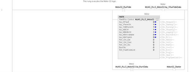
/* Execute the Motor 02 logic: get run feedback input, execute PMTR, send output to starter */
MyNG_PLLS_Motor02.Inp_1RunFdbkData := Motor02_RunFdbk;
PMTR (MyNG_PLLS_Motor02, 0, 0, 0, 0, 0);
Motor02_Starter := MyNG_PLLS_Motor02.Out_Run1Data;
/* Execute the Motor 03 logic: get run feedback input, execute PMTR, send output to starter */
MyNG_PLLS_Motor03.Inp_1RunFdbkData := Motor03_RunFdbk;
PMTR (MyNG_PLLS_Motor03, 0, 0, 0, 0, 0);
Motor03_Starter := MyNG_PLLS_Motor03.Out_Run1Data;
/* Copy the Motor 01 Status to the PLLS array [0] */
MyNG_PLLS_Motors[0].Sts_Available := MyNG_PLLS_Motor01.Sts_Available;
MyNG_PLLS_Motors[0].Sts_Stopped := MyNG_PLLS_Motor01.Sts_Stopped;
MyNG_PLLS_Motors[0].Sts_Starting := MyNG_PLLS_Motor01.Sts_Starting1;
MyNG_PLLS_Motors[0].Sts_Running := MyNG_PLLS_Motor01.Sts_Running1;
MyNG_PLLS_Motors[0].Sts_Stopping := MyNG_PLLS_Motor01.Sts_Stopping;
/* Copy the Motor 02 Status to the PLLS array [1] */
MyNG_PLLS_Motors[1].Sts_Available := MyNG_PLLS_Motor02.Sts_Available;
MyNG_PLLS_Motors[1].Sts_Stopped := MyNG_PLLS_Motor02.Sts_Stopped;
MyNG_PLLS_Motors[1].Sts_Starting := MyNG_PLLS_Motor02.Sts_Starting1;
MyNG_PLLS_Motors[1].Sts_Running := MyNG_PLLS_Motor02.Sts_Running1;
MyNG_PLLS_Motors[1].Sts_Stopping := MyNG_PLLS_Motor02.Sts_Stopping;
/* Copy the Motor 03 Status to the PLLS array [2] */
MyNG_PLLS_Motors[2].Sts_Available := MyNG_PLLS_Motor03.Sts_Available;
MyNG_PLLS_Motors[2].Sts_Stopped := MyNG_PLLS_Motor03.Sts_Stopped;
MyNG_PLLS_Motors[2].Sts_Starting := MyNG_PLLS_Motor03.Sts_Starting1;
MyNG_PLLS_Motors[2].Sts_Running := MyNG_PLLS_Motor03.Sts_Running1;
MyNG_PLLS_Motors[2].Sts_Stopping := MyNG_PLLS_Motor03.Sts_Stopping;
/* Now execute the Lead / Lag / Standby instruction */
PLLS (MyNG_PLLS, MyNG_PLLS_Motors, 0);
/* Now take the commands coming out of PLLS and forward them to the PMTR instances */
/* Program commands to Motor 01: */
/* Forward the Program Lock command: */
if (MyNG_PLLS_Motors[0].PCmd_Lock)
then
MyNG_PLLS_Motors[0].PCmd_Lock := 0;
MyNG_PLLS_Motor01.PCmd_Lock := 1;
end_if;
/* Forward the Program Unlock command: */
if (MyNG_PLLS_Motors[0].PCmd_Unlock)
then
MyNG_PLLS_Motors[0].PCmd_Unlock := 0;
MyNG_PLLS_Motor01.PCmd_Unlock := 1;
end_if;
/* Forward the Program Start command: */
if (MyNG_PLLS_Motors[0].PCmd_Start)
then
MyNG_PLLS_Motors[0].PCmd_Start := 0;
MyNG_PLLS_Motor01.PCmd_Start1 := 1;
end_if;
/* Forward the Program Stop command: */
if (MyNG_PLLS_Motors[0].PCmd_Stop)
then
MyNG_PLLS_Motors[0].PCmd_Stop := 0;
MyNG_PLLS_Motor01.PCmd_Stop := 1;
end_if;
/* Program commands to Motor 02: */
/* Forward the Program Lock command: */
if (MyNG_PLLS_Motors[1].PCmd_Lock)
then
MyNG_PLLS_Motors[1].PCmd_Lock := 0;
MyNG_PLLS_Motor02.PCmd_Lock := 1;
end_if;
/* Forward the Program Unlock command: */
if (MyNG_PLLS_Motors[1].PCmd_Unlock)
then
MyNG_PLLS_Motors[1].PCmd_Unlock := 0;
MyNG_PLLS_Motor02.PCmd_Unlock := 1;
end_if;
/* Forward the Program Start command: */
if (MyNG_PLLS_Motors[1].PCmd_Start)
then
MyNG_PLLS_Motors[1].PCmd_Start := 0;
MyNG_PLLS_Motor02.PCmd_Start1 := 1;
end_if;
/* Forward the Program Stop command: */
if (MyNG_PLLS_Motors[1].PCmd_Stop)
then
MyNG_PLLS_Motors[1].PCmd_Stop := 0;
MyNG_PLLS_Motor02.PCmd_Stop := 1;
end_if;
/* Program commands to Motor 03: */
/* Forward the Program Lock command: */
if (MyNG_PLLS_Motors[2].PCmd_Lock)
then
MyNG_PLLS_Motors[2].PCmd_Lock := 0;
MyNG_PLLS_Motor03.PCmd_Lock := 1;
end_if;
/* Forward the Program Unlock command: */
if (MyNG_PLLS_Motors[2].PCmd_Unlock)
then
MyNG_PLLS_Motors[2].PCmd_Unlock := 0;
MyNG_PLLS_Motor03.PCmd_Unlock := 1;
end_if;
/* Forward the Program Start command: */
if (MyNG_PLLS_Motors[2].PCmd_Start)
then
MyNG_PLLS_Motors[2].PCmd_Start := 0;
MyNG_PLLS_Motor03.PCmd_Start1 := 1;
end_if;
/* Forward the Program Stop command: */
if (MyNG_PLLS_Motors[2].PCmd_Stop)
then
MyNG_PLLS_Motors[2].PCmd_Stop := 0;
MyNG_PLLS_Motor03.PCmd_Stop := 1;
end_if;
Provide Feedback