- Studio 5000 Logix Designer
- Tasks, programs, and routines
- Add-On Instructions
- Controller Organizer
- Logical Organizer
- Alarms
- Tag-based alarms
- Tag Editor and Data Monitor
- Configure settings for Tag Editor and Data Monitor
- Equipment phases
- Equipment Sequences
- Equipment Sequence Diagrams
- Ladder Editor
- Structured Text Editor
- Sequential Function Chart Editor
- Define the steps of an SFC process
- PlantPAx instruction properties
- Controller Properties
- Editing Controller Properties
- Controller Security
- Source Protection
- License Source Protection for Routines and Add-On Instructions
- Module Information
- 1756 ControlLogix I/O Modules
- Instruction Set
Process n-Position Device (PNPOS)
This information applies to the CompactLogix 5380P and ControlLogix 5580P controllers.
The Process n-Position Device (PNPOS) instruction controls and monitors feedback from a circular or linear discrete device with up to 30 positions. The PNPOS instruction provides outputs to select an individual position and outputs to move toward increasing positions (clockwise for a circular device) or decreasing positions (counterclockwise for a circular device).
Basic functionality
These drawings illustrate the basic functionality of the PNPOS instruction.
Linear Device Outputs (7-position device):

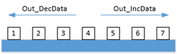
Circular Device Outputs (7-position device):

For linear devices, the PNPOS instruction can be configured to return to Position 1 on every move, approaching the target position from the same side on each move to improve position repeatability, or move directly to the new position.
For circular devices, the PNPOS instruction can be configured to move only clockwise to increase positions (for example, 28, 29, 30, 1, 2…) or both directions by using the shortest move (for example, clockwise from 28 to 1: 28, 29, 30, 1; or counterclockwise from 2 to 29: 2, 1, 30, 29).
Use the PNPOS instruction to:
- Control and monitor a multi-position device (up to thirty positions), such as rotary valves, and other devices with multiple fixed positions.
- Monitor limit switches or other position feedback and display actual device position.
- Check for failure to reach the requested position within a configured time. Provide Alarm on Position Failure.
- Monitor Permissive conditions to allow moving to a new position.
- Monitor Interlock conditions to de-energize the device, or to request the device to return to Position 1. Provide an Interlock Trip Alarm if an interlock condition causes the device to de-energize or return to Position 1.
- Provide outputs to request each position and provide outputs for increasing and decreasing position.
- Provide outputs to sequence indexing cylinders for devices that use pneumatic or hydraulic devices to step through positions. The cylinders work in an Extend, Shift, Retract, Shift sequence to engage the device, and step it to the next position. The cylinder sequence reverses the Shift directions when driving circular devices counterclockwise (for devices that support bidirectional operation).
- Optionally provide handling of a position lock or seal that must be driven to an unlocked or unsealed state before moving the device and returned to a locked or sealed state after the move is completed.
- Provide capability for maintenance personnel to take the device out of service.
- If the optional lock or seal is used, provide position feedback for the lock or seal to verify the locked or unlocked state at appropriate times. Provide Alarm for Lock Failure.
- Provide a virtualization capability, responding as if a working device were present while keeping outputs de-energized. The virtualization capability can be used for activities such as system testing, operator training, or as part of a full process virtualization.
- Monitor for I/O communication faults and provide an I/O Fault Alarm.
- Provide an Available status for use by automation logic so the logic knows when it has control of the device.
- Provide maintenance capabilities, such as the ability to bypass any bypassable interlocks or permissives or temporarily disable feedback checking.
- Operate from Hand, Maintenance, Override, External, Program, and Operator command sources.
Available Languages
Ladder Diagram

Function Block Diagram

Structured Text
PNPOS(PNPOSTag, BusObj);
Operands
IMPORTANT:
Unexpected operation may occur if:
- Output tag operands are overwritten.
- Members of a structure operand are overwritten.
- Except when specified, structure operands are shared by multiple instructions.
There are data conversion rules for mixing numeric data types within an instruction. See Data conversions.
Configuration Operands
Operand | Type | Format | Description |
|---|---|---|---|
PlantPAx ControlPlantPAx Control | P_DISCRETE_N_POSITION | tag | Data structure required for proper operation of instruction. |
BusObj | BUS_OBJ | tag | Bus component. |
P_DISCRETE_N_POSITION Structure
Public members are standard, visible tag members that are programmatically accessible. Private, hidden members are used in HMI faceplates and are not programmatically accessible. Private members are listed in separate tables after public members.
Public Input Members | Data Type | FBD Default Visibility | FBD Wiring required | Usage | Description |
|---|---|---|---|---|---|
EnableIn | BOOL | Not Visible | Not Required | Input | Enable Input - System Defined Parameter Default is true. |
Inp_InitializeReq | BOOL | Not Visible | Not Required | Input | 1 = Request to initialize the instruction. The instruction is normally initialized in instruction first run. Use this request when reinitialization is needed. The instruction clears this operand automatically. Default is true. |
Inp_OwnerCmd | DINT | Not Visible | Not Required | Input | Owner device command (bitmapped): All bits off = None, .10 = Operator Lock, .11 = Operator Unlock, .12 = Program Lock, .13 = Program Unlock, .14 = Acquire Maintenance, .15 = Release Maintenance, .16 = Acquire External, .17 = Release External, .29 = Echo. Default is 0. |
Inp_Pos01FdbkData | BOOL | Visible | Not Required | Input | Position 1 feedback: 1 = Device is confirmed at Position 1. Default is false. |
Inp_Pos02FdbkData | BOOL | Visible | Not Required | Input | Position 2 feedback: 1 = Device is confirmed at Position 2. Default is false. |
Inp_Pos03FdbkData | BOOL | Visible | Not Required | Input | Position 3 feedback: 1 = Device is confirmed at Position 3. Default is false. |
Inp_Pos04FdbkData | BOOL | Not Visible | Not Required | Input | Position 4 feedback: 1 = Device is confirmed at Position 4. Default is false. |
Inp_Pos05FdbkData | BOOL | Not Visible | Not Required | Input | Position 5 feedback: 1 = Device is confirmed at Position 5. Default is false. |
Inp_Pos06FdbkData | BOOL | Not Visible | Not Required | Input | Position 6 feedback: 1 = Device is confirmed at Position 6. Default is false. |
Inp_Pos07FdbkData | BOOL | Not Visible | Not Required | Input | Position 7 feedback: 1 = Device is confirmed at Position 7. Default is false. |
Inp_Pos08FdbkData | BOOL | Not Visible | Not Required | Input | Position 8 feedback: 1 = Device is confirmed at Position 8. Default is false. |
Inp_Pos09FdbkData | BOOL | Not Visible | Not Required | Input | Position 9 feedback: 1 = Device is confirmed at Position 9. Default is false. |
Inp_Pos10FdbkData | BOOL | Not Visible | Not Required | Input | Position 10 feedback: 1 = Device is confirmed at Position 10. Default is false. |
Inp_Pos11FdbkData | BOOL | Not Visible | Not Required | Input | Position 11 feedback: 1 = Device is confirmed at Position 11. Default is false. |
Inp_Pos12FdbkData | BOOL | Not Visible | Not Required | Input | Position 12 feedback: 1 = Device is confirmed at Position 12. Default is false. |
Inp_Pos13FdbkData | BOOL | Not Visible | Not Required | Input | Position 13 feedback: 1 = Device is confirmed at Position 13. Default is false. |
Inp_Pos14FdbkData | BOOL | Not Visible | Not Required | Input | Position 14 feedback: 1 = Device is confirmed at Position 14. Default is false. |
Inp_Pos15FdbkData | BOOL | Not Visible | Not Required | Input | Position 15 feedback: 1 = Device is confirmed at Position 15. Default is false. |
Inp_Pos16FdbkData | BOOL | Not Visible | Not Required | Input | Position 16 feedback: 1 = Device is confirmed at Position 16. Default is false. |
Inp_Pos17FdbkData | BOOL | Not Visible | Not Required | Input | Position 17 feedback: 1 = Device is confirmed at Position 17. Default is false. |
Inp_Pos18FdbkData | BOOL | Not Visible | Not Required | Input | Position 18 feedback: 1 = Device is confirmed at Position 18. Default is false. |
Inp_Pos19FdbkData | BOOL | Not Visible | Not Required | Input | Position 19 feedback: 1 = Device is confirmed at Position 19. Default is false. |
Inp_Pos20FdbkData | BOOL | Not Visible | Not Required | Input | Position 20 feedback: 1 = Device is confirmed at Position 20. Default is false. |
Inp_Pos21FdbkData | BOOL | Not Visible | Not Required | Input | Position 21 feedback: 1 = Device is confirmed at Position 21. Default is false. |
Inp_Pos22FdbkData | BOOL | Not Visible | Not Required | Input | Position 22 feedback: 1 = Device is confirmed at Position 22. Default is false. |
Inp_Pos23FdbkData | BOOL | Not Visible | Not Required | Input | Position 23 feedback: 1 = Device is confirmed at Position 23. Default is false. |
Inp_Pos24FdbkData | BOOL | Not Visible | Not Required | Input | Position 24 feedback: 1 = Device is confirmed at Position 24. Default is false. |
Inp_Pos25FdbkData | BOOL | Not Visible | Not Required | Input | Position 25 feedback: 1 = Device is confirmed at Position 25. Default is false. |
Inp_Pos26FdbkData | BOOL | Not Visible | Not Required | Input | Position 26 feedback: 1 = Device is confirmed at Position 26. Default is false. |
Inp_Pos27FdbkData | BOOL | Not Visible | Not Required | Input | Position 27 feedback: 1 = Device is confirmed at Position 27. Default is false. |
Inp_Pos28FdbkData | BOOL | Not Visible | Not Required | Input | Position 28 feedback: 1 = Device is confirmed at Position 28. Default is false. |
Inp_Pos29FdbkData | BOOL | Not Visible | Not Required | Input | Position 29 feedback: 1 = Device is confirmed at Position 29. Default is false. |
Inp_Pos30FdbkData | BOOL | Not Visible | Not Required | Input | Position 30 feedback: 1 = Device is confirmed at Position 30. Default is false. |
Inp_LockFdbkData | BOOL | Not Visible | Not Required | Input | 1 = Device is confirmed locked/sealed in position. Default is false. |
Inp_UnlockFdbkData | BOOL | Not Visible | Not Required | Input | 1 = Device is confirmed unlocked/unsealed and is free to move. Default is false. |
Inp_CylExtFdbkData | BOOL | Not Visible | Not Required | Input | 1 = Device indexing cylinder is confirmed extended. Default is false. |
Inp_CylRetrFdbkData | BOOL | Not Visible | Not Required | Input | 1 = Device indexing cylinder is confirmed retracted. Default is false. |
Inp_CylLeftFdbkData | BOOL | Not Visible | Not Required | Input | 1 = Device indexing cylinder is confirmed in left (increasing) position. Default is false. |
Inp_CylRightFdbkData | BOOL | Not Visible | Not Required | Input | 1 = Device indexing cylinder is confirmed in right (decreasing) position. Default is false. |
Inp_IOFault | BOOL | Visible | Not Required | Input | 1 = I/O communication is faulted, 0 = I/O communication is OK. Default is false. |
Inp_PermOK | BOOL | Visible | Not Required | Input | 1 = Permissives are OK, device can energize. Default is true. |
Inp_NBPermOK | BOOL | Visible | Not Required | Input | 1 = Non-bypassable permissives are OK, device can energize. Default is true. |
Inp_IntlkOK | BOOL | Visible | Not Required | Input | 1 = Interlocks are OK, device can energize, 0 = Interlocks are not OK, device must de-energize or drive to Position 1. Default is true. |
Inp_NBIntlkOK | BOOL | Visible | Not Required | Input | 1 = Non-bypassable interlocks OK, device can energize, 0 = Interlocks are not OK, device must de-energize or drive to Position 1. Default is true. |
Inp_IntlkAvailable | BOOL | Visible | Not Required | Input | 1 = Interlock availability is OK, show Sts_IntlkAvailable if device is ready except for interlocks. Default is false. |
Inp_IntlkTripInh | BOOL | Visible | Not Required | Input | 1 = Inhibit reporting of Sts_IntlkTrip and interlock trip alarm. Default is false. |
Inp_RdyReset | BOOL | Not Visible | Not Required | Input | 1 = Related object, reset by this object, is ready to be reset. Default is false. |
Inp_Hand | BOOL | Not Visible | Not Required | Input | 1 = Acquire Hand command source (typically hardwired local), 0 = Release Hand. Default is false. |
Inp_Ovrd | BOOL | Not Visible | Not Required | Input | 1 = Acquire Override command source (higher priority program logic), 0 = Release Override. Default is false. |
Inp_OvrdCmd | SINT | Not Visible | Not Required | Input | Override device command: 0 = No command, 1 = Position 1, 2 = Position 2, ..., 30 = Position 30. Default is 0. |
Inp_ExtInh | BOOL | Not Visible | Not Required | Input | 1 = Inhibit External command source acquisition, 0 = Allow External acquisition. Default is false. |
Inp_HornInh | BOOL | Not Visible | Not Required | Input | 1 = Inhibit audible alert, 0 = Allow audible alert. Default is false. |
Inp_Reset | BOOL | Not Visible | Not Required | Input | 1 = Reset shed latches and cleared alarms. Default is false. |
Cfg_AllowDisable | BOOL | Not Visible | Not Required | Input | 1 = Allow Maintenance to disable alarms. Default is true. |
Cfg_AllowShelve | BOOL | Not Visible | Not Required | Input | 1 = Allow Operator to shelve alarms. Default is true. |
Cfg_NumPos | SINT | Not Visible | Not Required | Input | Number of device positions. Valid = 2 to 30. Default is 3. |
Cfg_Circ | BOOL | Not Visible | Not Required | Input | 1 = Positions are circular (rotary device, after Position n is Position 1), 0 = linear device (Position 1 and Position n are at ends of travel). Default is false. |
Cfg_CWOnly | BOOL | Not Visible | Not Required | Input | 1 = Circular (rotary) device can only rotate "clockwise", 0 = circular device is bidirectional, use shortest path. Default is false. |
Cfg_ViaPos01 | BOOL | Not Visible | Not Required | Input | 1 = Drive linear device to Position 1 on every move, 0 = move direct to set position. Default is false. |
Cfg_IntlkToPos01 | BOOL | Not Visible | Not Required | Input | 1 = Drive to Position 1 on interlock not OK, 0 = De-energize only on interlock not OK. Default is false. |
Cfg_OutPosLatch | BOOL | Not Visible | Not Required | Input | 1 = Latch position output until a new target position is set, 0 = clear position output upon reaching target position. Default is false. |
Cfg_HasLock | BOOL | Not Visible | Not Required | Input | 1 = Device has a lock or seal which must be unlocked/unsealed before moving. Default is false. |
Cfg_HasPosFdbk | BOOL | Not Visible | Not Required | Input | 1 = Device has position feedback for all positions. Default is false. |
Cfg_UsePosFdbk | BOOL | Not Visible | Not Required | Input | 1 = Use position feedback to verify device reached target position. Default is false. |
Cfg_HasLockFdbk | BOOL | Not Visible | Not Required | Input | 1 = Device has locked/unlocked feedback. Default is false. |
Cfg_UseLockFdbk | BOOL | Not Visible | Not Required | Input | 1 = Use lock feedback to verify locking and unlocking of device. Default is false. |
Cfg_HasCylFdbk | BOOL | Not Visible | Not Required | Input | 1 = Device indexing cylinders have position feedback. Default is false. |
Cfg_UseCylFdbk | BOOL | Not Visible | Not Required | Input | 1 = Use indexing cylinder position feedback to verify cylinder motion. Default is false. |
Cfg_HasPermObj | BOOL | Not Visible | Not Required | Input | 1 = Tells HMI an object is connected to Inp_Perm inputs, enable navigation. Default is false. |
Cfg_HasIntlkObj | BOOL | Not Visible | Not Required | Input | 1 = Tells HMI an object is connected to Inp_Intlk inputs, enable navigation. Default is false. |
Cfg_HasMoreObj | BOOL | Not Visible | Not Required | Input | 1 = Tells HMI an object with more information is available, enable navigation. Default is false. |
Cfg_OperPos01Prio | BOOL | Not Visible | Not Required | Input | 1 = OSet_Pos setting to Position 1 is accepted any time, 0 = OSet_Pos is accepted only when Operator command source is selected. Default is false. |
Cfg_ExtPos01Prio | BOOL | Not Visible | Not Required | Input | 1 = XSet_Pos setting to Position 1 is accepted any time, 0 = XSet_Pos is accepted only when External command source is selected. Default is false. |
Cfg_OSetResets | BOOL | Not Visible | Not Required | Input | 1 = A new Operator state command resets fault, 0 = A reset command is required to clear fault. Default is false. |
Cfg_XSetResets | BOOL | Not Visible | Not Required | Input | 1 = A new External state command resets fault, 0 = A reset command is required to clear fault. Default is false. |
Cfg_SetDuringMove | BOOL | Not Visible | Not Required | Input | 1 = New position setting received during move is accepted, 0 = Must wait for previous move to complete. Default is false. |
Cfg_OvrdPermIntlk | BOOL | Not Visible | Not Required | Input | 1 = Override ignores bypassable permissives and interlocks, 0 = Override uses all permissives and interlocks. Default is false. |
Cfg_ShedOnPosFail | BOOL | Not Visible | Not Required | Input | 1 = De-energize device and alarm on position fail, 0 = Alarm only. Default is true. |
Cfg_ShedOnLockFail | BOOL | Not Visible | Not Required | Input | 1 = De-energize device and alarm on lock fail, 0 = Alarm only. Default is true. |
Cfg_ShedOnIOFault | BOOL | Not Visible | Not Required | Input | 1 = De-energize device and alarm on I/O fault, 0 = Alarm only. Default is true. |
Cfg_HornOnChange | BOOL | Not Visible | Not Required | Input | 1 = Sound horn on any position change, 0 = Sound horn only on leaving Position 1. Default is false. |
Cfg_HasOper | BOOL | Not Visible | Not Required | Input | 1 = Operator (unlocked) command source exists, can be selected. Default is true. |
Cfg_HasOperLocked | BOOL | Not Visible | Not Required | Input | 1 = Operator Locked command source exists, can be selected. Default is true. |
Cfg_HasProg | BOOL | Not Visible | Not Required | Input | 1 = Program (unlocked) command source exists, can be selected. Default is true. |
Cfg_HasProgLocked | BOOL | Not Visible | Not Required | Input | 1 = Program Locked command source exists, can be selected. Default is true. |
Cfg_HasExt | BOOL | Not Visible | Not Required | Input | 1 = External command source exists, can be selected. Default is false. |
Cfg_HasMaint | BOOL | Not Visible | Not Required | Input | 1 = Maintenance command source exists, can be selected. Default is true. |
Cfg_HasMaintOoS | BOOL | Not Visible | Not Required | Input | 1 = Maintenance Out of Service exists, can be selected. Default is true. |
Cfg_OvrdOverLock | BOOL | Not Visible | Not Required | Input | 1 = Override supersedes Program/Operator Locked, 0 = Don't supersede Program/Operator Locked. Default is true. |
Cfg_ExtOverLock | BOOL | Not Visible | Not Required | Input | 1 = External supersedes Program/Operator Locked, 0 = Don't supersede Program/Operator Locked. Default is false. |
Cfg_ProgPwrUp | BOOL | Not Visible | Not Required | Input | 1 = Power up to Program command source, 0 = Power up to Operator command source. Default is false. |
Cfg_ProgNormal | BOOL | Not Visible | Not Required | Input | Normal command source: 1 = Program, 0 = Operator. Default is false. |
Cfg_PCmdPriority | BOOL | Not Visible | Not Required | Input | Command priority: 1 = Program commands win, 0 = Operator commands win. Default is false. |
Cfg_PCmdProgAsLevel | BOOL | Not Visible | Not Required | Input | 1 = Program/Operator selection follows PCmd_Prog as level (1 for Program, 0 for Operator), 0 = PCmd_Prog is used as edge to select Program, PCmd_Oper selects Operator. Default is false. |
Cfg_PCmdLockAsLevel | BOOL | Not Visible | Not Required | Input | 1 = Program lock selection follows PCmd_Lock as level (1 for locked, 0 for unlocked), 0 = PCmd_Lock is used as edge to select Program Locked, PCmd_Unlock selects Program (unlocked). Default is false. |
Cfg_ExtAcqAsLevel | BOOL | Not Visible | Not Required | Input | 1 = External selection follows XCmd_Acq as level (1 to acquire External, 0 to release External), 0 = XCmd_Acq is used as edge to acquire External, XCmd_Rel is used to release External. Default is false. |
Cfg_Retries | SINT | Not Visible | Not Required | Input | Number of retries via Position 1 before declaring failure, Valid = 0 to 3, 0 = Don't retry. Default is 3. |
Cfg_ExtendDelay | REAL | Not Visible | Not Required | Input | Delay before extending cylinder to engage for move (seconds). Valid = 0.0 to 2147483.0. Default is 0.0. |
Cfg_VerifyDelay | REAL | Not Visible | Not Required | Input | Delay to verify device has settled in commanded position (seconds). Valid = 0.0 to 2147483.0. Default is 1.0. |
Cfg_PosCheckTime | REAL | Not Visible | Not Required | Input | Time to receive position feedback before declaring failure (seconds). Valid = 0.0 to 2147483.0. Default is 30.0. |
Cfg_LockCheckTime | REAL | Not Visible | Not Required | Input | Time to receive locked/unlocked feedback before declaring lock failure (seconds). Valid = 0.0 to 2147483.0. Default is 5.0. |
Cfg_VirtualPosTime | REAL | Not Visible | Not Required | Input | Time to simulate reaching target position when virtualized (seconds). Valid = 0.0 to 2147483.0. Default is 1.0. |
Cfg_VirtualLockTime | REAL | Not Visible | Not Required | Input | Time to simulate lock or unlock when virtualized (seconds). Valid = 0.0 to 2147483.0. Default is 1.0. |
Cfg_VirtualCylTime | REAL | Not Visible | Not Required | Input | Time to simulate index cylinder feedback when virtualized (seconds). Valid = 0.0 to 21474830. Default is 0.5. |
Cfg_StartHornTime | REAL | Not Visible | Not Required | Input | Time to sound audible on device position change (seconds). Valid = 0.0 to 1000.0, 0.0 = Disabled. Default is 0.0. |
Cfg_CnfrmReqd | SINT | Not Visible | Not Required | Input | Operator command confirmation or e-signature type required: 0 = None, 1 = Command confirmation required, 2 = Performer e-signature required, 3 = Performer and approver e-signature required. Default is 0. |
PSet_Owner | DINT | Not Visible | Not Required | Input | Program ownership request: Non-zero Owner ID = Acquire, 0 = Release. Default is 0. |
PSet_Pos | SINT | Not Visible | Not Required | Input | Program Setting of commanded position 1 to 30, 0 = No command. The instruction clears this operand automatically. Default is 0. |
PCmd_Virtual | BOOL | Not Visible | Not Required | Input | Program Command to select Virtual (simulated) device operation. The instruction clears this operand automatically. Default is false. |
PCmd_Physical | BOOL | Not Visible | Not Required | Input | Program Command to select Physical device operation (not simulated). The instruction clears this operand automatically. Default is false. |
PCmd_Reset | BOOL | Not Visible | Not Required | Input | Program Command to reset shed latches and returned-to-normal latched alarms. The instruction clears this operand automatically. Default is false. |
PCmd_Prog | BOOL | Not Visible | Not Required | Input | Program Command to select Program command source. The instruction clears this operand automatically if Cfg_PCmdProgAsLevel = 0. Default is false. |
PCmd_Oper | BOOL | Not Visible | Not Required | Input | Program Command to select Operator command source. The instruction clears this operand automatically. Default is false. |
PCmd_Lock | BOOL | Not Visible | Not Required | Input | Program Command to lock Program command source and disallow Operator. The instruction clears this operand automatically if Cfg_PCmdLockAsLevel = 0. Default is false. |
PCmd_Unlock | BOOL | Not Visible | Not Required | Input | Program Command to unlock Program command source and allow Operator to acquire. The instruction clears this operand automatically. Default is false. |
PCmd_Normal | BOOL | Not Visible | Not Required | Input | Program Command to select normal command source (Operator or Program). The instruction clears this operand automatically. Default is false. |
XSet_Pos | SINT | Not Visible | Not Required | Input | External Setting of commanded position 1 to 30, 0 = No command. The instruction clears this operand automatically. Default is 0. |
XCmd_Acq | BOOL | Not Visible | Not Required | Input | External Command to acquire command source. The instruction clears this operand automatically if Cfg_ExtAcqAsLevel = 0. Default is false. |
XCmd_Rel | BOOL | Not Visible | Not Required | Input | External Command to release command source, accepted if Cfg_ExtAcqAsLevel = 0. The instruction clears this operand automatically. Default is false. |
XCmd_Reset | BOOL | Not Visible | Not Required | Input | External Command to reset shed latches and returned-to-normal latched alarms. The instruction clears this operand automatically. Default is false. |
XCmd_ResetAckAll | BOOL | Not Visible | Not Required | Input | External Command to acknowledge all alarms and reset latched alarms and shed conditions. The instruction clears this operand automatically. Default is false. |
Public Output Members | Data Type | FBD Default Visibility | FBD Wiring required | Usage | Description |
|---|---|---|---|---|---|
EnableOut | BOOL | Not Visible | Not Required | Output | Enable Output - System Defined Parameter |
Out_Pos01Data | BOOL | Visible | Not Required | Output | Output to go to Position 1. |
Out_Pos02Data | BOOL | Visible | Not Required | Output | Output to go to Position 2. |
Out_Pos03Data | BOOL | Visible | Not Required | Output | Output to go to Position 3. |
Out_Pos04Data | BOOL | Not Visible | Not Required | Output | Output to go to Position 4. |
Out_Pos05Data | BOOL | Not Visible | Not Required | Output | Output to go to Position 5. |
Out_Pos06Data | BOOL | Not Visible | Not Required | Output | Output to go to Position 6. |
Out_Pos07Data | BOOL | Not Visible | Not Required | Output | Output to go to Position 7. |
Out_Pos08Data | BOOL | Not Visible | Not Required | Output | Output to go to Position 8 . |
Out_Pos09Data | BOOL | Not Visible | Not Required | Output | Output to go to Position 9. |
Out_Pos10Data | BOOL | Not Visible | Not Required | Output | Output to go to Position 10. |
Out_Pos11Data | BOOL | Not Visible | Not Required | Output | Output to go to Position 11. |
Out_Pos12Data | BOOL | Not Visible | Not Required | Output | Output to go to Position 12. |
Out_Pos13Data | BOOL | Not Visible | Not Required | Output | Output to go to Position 13. |
Out_Pos14Data | BOOL | Not Visible | Not Required | Output | Output to go to Position 14. |
Out_Pos15Data | BOOL | Not Visible | Not Required | Output | Output to go to Position 15. |
Out_Pos16Data | BOOL | Not Visible | Not Required | Output | Output to go to Position 16. |
Out_Pos17Data | BOOL | Not Visible | Not Required | Output | Output to go to Position 17. |
Out_Pos18Data | BOOL | Not Visible | Not Required | Output | Output to go to Position 18 . |
Out_Pos19Data | BOOL | Not Visible | Not Required | Output | Output to go to Position 19. |
Out_Pos20Data | BOOL | Not Visible | Not Required | Output | Output to go to Position 20. |
Out_Pos21Data | BOOL | Not Visible | Not Required | Output | Output to go to Position 21. |
Out_Pos22Data | BOOL | Not Visible | Not Required | Output | Output to go to Position 22. |
Out_Pos23Data | BOOL | Not Visible | Not Required | Output | Output to go to Position 23. |
Out_Pos24Data | BOOL | Not Visible | Not Required | Output | Output to go to Position 24. |
Out_Pos25Data | BOOL | Not Visible | Not Required | Output | Output to go to Position 25. |
Out_Pos26Data | BOOL | Not Visible | Not Required | Output | Output to go to Position 26. |
Out_Pos27Data | BOOL | Not Visible | Not Required | Output | Output to go to Position 27. |
Out_Pos28Data | BOOL | Not Visible | Not Required | Output | Output to go to Position 28. |
Out_Pos29Data | BOOL | Not Visible | Not Required | Output | Output to go to Position 29. |
Out_Pos30Data | BOOL | Not Visible | Not Required | Output | Output to go to Position 30. |
Out_IncData | BOOL | Visible | Not Required | Output | Output to drive to increasing position (clockwise). |
Out_DecData | BOOL | Visible | Not Required | Output | Output to drive to decreasing position (counter-clockwise). |
Out_UnlockData | BOOL | Not Visible | Not Required | Output | Output to unlock/unseal device. |
Out_LockData | BOOL | Not Visible | Not Required | Output | Output to lock/seal device. |
Out_CylExtendData | BOOL | Not Visible | Not Required | Output | Output to extend cylinder to engage position indexing device. |
Out_CylRetractData | BOOL | Not Visible | Not Required | Output | Output to retract cylinder to disengage position indexing device. |
Out_CylLeftData | BOOL | Not Visible | Not Required | Output | Output to index device to left (increase position). |
Out_CylRightData | BOOL | Not Visible | Not Required | Output | Output to index device to right (decrease position). |
Out_HornData | BOOL | Not Visible | Not Required | Output | Output to sound horn prior to commanded position change. |
Out_Reset | BOOL | Not Visible | Not Required | Output | 1 = Reset command has been received and accepted. |
Out_OwnerSts | DINT | Not Visible | Not Required | Output | Status of command source, owner command handshake and ready status (bitmapped): All bits off = None, .10 = Operator Lock, .11 = Operator Unlock, .12 = Program Lock, .13 = Program Unlock, .14 = Acquire Maintenance, .15 = Release Maintenance, .16 = Acquire External, .17 = Release External, .18 = Has Maintenance, .19 = External Override Lock, .20 = Has External, .21 = Has Operator, .22 = Has Operator Locked, .23 = Has Program, .24 = Has Program Locked, .29 = Echo, .30 = Not Ready. |
Sts_Initialized | BOOL | Not Visible | Not Required | Output | 1 = Instruction is initialized. 0 = Use Inp_InitializeReq to reinitialize. |
Sts_Pos01 | BOOL | Visible | Not Required | Output | 1 = Device confirmed in Position 1. |
Sts_Pos02 | BOOL | Visible | Not Required | Output | 1 = Device confirmed in Position 2. |
Sts_Pos03 | BOOL | Visible | Not Required | Output | 1 = Device confirmed in Position 3. |
Sts_Pos04 | BOOL | Not Visible | Not Required | Output | 1 = Device confirmed in Position 4. |
Sts_Pos05 | BOOL | Not Visible | Not Required | Output | 1 = Device confirmed in Position 5. |
Sts_Pos06 | BOOL | Not Visible | Not Required | Output | 1 = Device confirmed in Position 6. |
Sts_Pos07 | BOOL | Not Visible | Not Required | Output | 1 = Device confirmed in Position 7. |
Sts_Pos08 | BOOL | Not Visible | Not Required | Output | 1 = Device confirmed in Position 8. |
Sts_Pos09 | BOOL | Not Visible | Not Required | Output | 1 = Device confirmed in Position 9. |
Sts_Pos10 | BOOL | Not Visible | Not Required | Output | 1 = Device confirmed in Position 10. |
Sts_Pos11 | BOOL | Not Visible | Not Required | Output | 1 = Device confirmed in Position 11. |
Sts_Pos12 | BOOL | Not Visible | Not Required | Output | 1 = Device confirmed in Position 12. |
Sts_Pos13 | BOOL | Not Visible | Not Required | Output | 1 = Device confirmed in Position 13. |
Sts_Pos14 | BOOL | Not Visible | Not Required | Output | 1 = Device confirmed in Position 14. |
Sts_Pos15 | BOOL | Not Visible | Not Required | Output | 1 = Device confirmed in Position 15. |
Sts_Pos16 | BOOL | Not Visible | Not Required | Output | 1 = Device confirmed in Position 16. |
Sts_Pos17 | BOOL | Not Visible | Not Required | Output | 1 = Device confirmed in Position 17. |
Sts_Pos18 | BOOL | Not Visible | Not Required | Output | 1 = Device confirmed in Position 18. |
Sts_Pos19 | BOOL | Not Visible | Not Required | Output | 1 = Device confirmed in Position 19. |
Sts_Pos20 | BOOL | Not Visible | Not Required | Output | 1 = Device confirmed in Position 20. |
Sts_Pos21 | BOOL | Not Visible | Not Required | Output | 1 = Device confirmed in Position 21. |
Sts_Pos22 | BOOL | Not Visible | Not Required | Output | 1 = Device confirmed in Position 22. |
Sts_Pos23 | BOOL | Not Visible | Not Required | Output | 1 = Device confirmed in Position 23. |
Sts_Pos24 | BOOL | Not Visible | Not Required | Output | 1 = Device confirmed in Position 24. |
Sts_Pos25 | BOOL | Not Visible | Not Required | Output | 1 = Device confirmed in Position 25. |
Sts_Pos26 | BOOL | Not Visible | Not Required | Output | 1 = Device confirmed in Position 26. |
Sts_Pos27 | BOOL | Not Visible | Not Required | Output | 1 = Device confirmed in Position 27. |
Sts_Pos28 | BOOL | Not Visible | Not Required | Output | 1 = Device confirmed in Position 28. |
Sts_Pos29 | BOOL | Not Visible | Not Required | Output | 1 = Device confirmed in Position 29. |
Sts_Pos30 | BOOL | Not Visible | Not Required | Output | 1 = Device confirmed in Position 30. |
Sts_Moving | BOOL | Visible | Not Required | Output | 1 = Device moving to target position, not yet confirmed in position. |
Sts_Horn | BOOL | Not Visible | Not Required | Output | 1 = Sounding horn prior to commanded energize/position change. |
Sts_Virtual | BOOL | Not Visible | Not Required | Output | 1 = The instruction treats device as virtual, acting as if controlling a working device, but the outputs are kept de-energized, 0 = The instruction operates the physical device normally. |
SrcQ_IO | SINT | Not Visible | Not Required | Output | Source and quality of primary input or output: 0=Good, live, confirmed good 1=Good, live, assumed good 2=Good, no feedback, assumed good 8=Test, virtualized 9=Test, loopback 10=Test, manually entered 16=Uncertain, live, off-spec 17=Uncertain, substituted at device or bus 18=Uncertain, substituted at instruction 19=Uncertain, using last known good 20=Uncertain, using replacement value 32=Bad, signal failure 33=Bad, channel fault 34=Bad, module or communication fault 35=Bad, invalid configuration |
SrcQ | SINT | Not Visible | Not Required | Output | Source and quality of primary value or status: 0=Good, live, confirmed good 1=Good, live, assumed good 2=Good, no feedback, assumed good 8=Test, virtualized 9=Test, loopback 10=Test, manually entered 16=Uncertain, live, off-spec 17=Uncertain, substituted at device or bus 18=Uncertain, substituted at instruction 19=Uncertain, using last known good 20=Uncertain, using replacement value 32=Bad, signal failure 33=Bad, channel fault 34=Bad, module or communication fault 35=Bad, invalid configuration |
Sts_eCmd | SINT | Not Visible | Not Required | Output | Device command: 0 = None, 1 = Position 1, 2 = Position 2, ..., 30 = Position 30. |
Sts_eFdbk | SINT | Not Visible | Not Required | Output | Device feedback: 0 = Moving or unknown position, 1 = Position 1, 2 = Position 2, ..., 30 = Position 30, 31 = Multiple positions or invalid feedback. |
Sts_eSts | SINT | Not Visible | Not Required | Output | Device status: 0 = Powerup/Reset, 1 = Position 1, 2 = Position 2, ..., 30 = Position 30, 31 = Moving, 32 = Horn, 33 = Out of service. |
Sts_eFault | SINT | Not Visible | Not Required | Output | Device fault status: 0 = None, 16 = Position fail, 17 = Lock/Unlock fail, 32 = I/O fault, 34 = Configuration error. |
Sts_eState | SINT | Not Visible | Not Required | Output | Internal state: 0 = De-energized on powerup/interlock/shed, 1 = In position, 2 = Unlocking, 3 = Moving to Position 1, 4 = Moving to requested position, 5 = Locking, 6 = Faulted. |
Sts_eOutPos | SINT | Not Visible | Not Required | Output | State of position outputs to physical device: 0 = De-energized, 1 = Position 1, 2 = Position 2, ..., 30 = Position 30. |
Sts_eOutState | SINT | Not Visible | Not Required | Output | State of motion outputs to physical device: 0 = Maintain position, 1 = Unlock, 2 = Decrease position, 3 = Increase position, 4 = Lock, 5 = Horn. |
Sts_eNotify | SINT | Not Visible | Not Required | Output | Summary alarm status: 0 = Not in alarm, acknowledged, 1 = Not in alarm, unacknowledged or reset required, 2 = Low severity alarm, acknowledged, 3 = Low severity alarm, unacknowledged, 4 = Medium severity alarm, acknowledged, 5 = Medium severity alarm, unacknowledged, 6 = High severity alarm, acknowledged, 7 = High severity alarm, unacknowledged, 8 = Urgent severity alarm, acknowledged, 9 = Urgent severity alarm, unacknowledged. |
Sts_eNotifyAll | SINT | Not Visible | Not Required | Output | Summary alarm status including related objects: 0 = Not in alarm, acknowledged, 1 = Not in alarm, unacknowledged or reset required, 2 = Low severity alarm, acknowledged, 3 = Low severity alarm, unacknowledged, 4 = Medium severity alarm, acknowledged, 5 = Medium severity alarm, unacknowledged, 6 = High severity alarm, acknowledged, 7 = High severity alarm, unacknowledged, 8 = Urgent severity alarm, acknowledged, 9 = Urgent severity alarm, unacknowledged. |
Sts_eNotifyIOFault | SINT | Not Visible | Not Required | Output | I/O fault alarm status: 0 = Not in alarm, acknowledged, 1 = Not in alarm, unacknowledged or reset required, 2 = Low severity alarm, acknowledged, 3 = Low severity alarm, unacknowledged, 4 = Medium severity alarm, acknowledged, 5 = Medium severity alarm, unacknowledged, 6 = High severity alarm, acknowledged, 7 = High severity alarm, unacknowledged, 8 = Urgent severity alarm, acknowledged, 9 = Urgent severity alarm, unacknowledged. |
Sts_eNotifyPosFail | SINT | Not Visible | Not Required | Output | Device position fail alarm status: 0 = Not in alarm, acknowledged, 1 = Not in alarm, unacknowledged or reset required, 2 = Low severity alarm, acknowledged, 3 = Low severity alarm, unacknowledged, 4 = Medium severity alarm, acknowledged, 5 = Medium severity alarm, unacknowledged, 6 = High severity alarm, acknowledged, 7 = High severity alarm, unacknowledged, 8 = Urgent severity alarm, acknowledged, 9 = Urgent severity alarm, unacknowledged. |
Sts_eNotifyLockFail | SINT | Not Visible | Not Required | Output | Device lock/seal fail alarm status: 0 = Not in alarm, acknowledged, 1 = Not in alarm, unacknowledged or reset required, 2 = Low severity alarm, acknowledged, 3 = Low severity alarm, unacknowledged, 4 = Medium severity alarm, acknowledged, 5 = Medium severity alarm, unacknowledged, 6 = High severity alarm, acknowledged, 7 = High severity alarm, unacknowledged, 8 = Urgent severity alarm, acknowledged, 9 = Urgent severity alarm, unacknowledged. |
Sts_eNotifyIntlkTrip | SINT | Not Visible | Not Required | Output | Interlock trip alarm status: 0 = Not in alarm, acknowledged, 1 = Not in alarm, unacknowledged or reset required, 2 = Low severity alarm, acknowledged, 3 = Low severity alarm, unacknowledged, 4 = Medium severity alarm, acknowledged, 5 = Medium severity alarm, unacknowledged, 6 = High severity alarm, acknowledged, 7 = High severity alarm, unacknowledged, 8 = Urgent severity alarm, acknowledged, 9 = Urgent severity alarm, unacknowledged. |
Sts_UnackAlmCount | DINT | Not Visible | Not Required | Output | Count of unacknowledged alarms. |
Sts_eSrc | INT | Not Visible | Not Required | Output | Current command source: 0 = Logic not in use, 4 = Hand, 8 = Maintenance, 16 = Override, 32 = Program, 33 = Program Locked, 34 = Program default (Normal), 64 = Operator, 65 = Operator Locked, 66 = Operator default (Normal), 128 = Maintenance Out of Service, 129 = Programmed Out of Service (EnableIn false), 256 = External. |
Sts_bSrc | INT | Not Visible | Not Required | Output | Active command source selections (bitmapped, for HMI): .0 = Hand, .1 = Programmed Out of Service (EnableIn false), .2= Maintenance Out of Service, .3 = Maintenance, .4 = Override, .5 = External, .6 = Program Locked, .7 = Program (unlocked), .8 = Operator Locked, .9 = Operator (unlocked). |
Sts_Available | BOOL | Not Visible | Not Required | Output | 1 = Device has been acquired by Program and is ready and available for control. |
Sts_IntlkAvailable | BOOL | Not Visible | Not Required | Output | 1 = Device can be acquired by Program and is available for control when interlocks are OK. |
Sts_Bypass | BOOL | Not Visible | Not Required | Output | 1 = Bypassable interlocks and permissives are bypassed. |
Sts_BypActive | BOOL | Visible | Not Required | Output | 1 = Interlock/permissive bypassing is active (bypassed by command or in Maintenance command source). |
Sts_MaintByp | BOOL | Not Visible | Not Required | Output | 1 = Device has a maintenance bypass function active. |
Sts_NotRdy | BOOL | Visible | Not Required | Output | 1 = Device not ready, see Sts_NrdyXxx detail bits for reason. |
Sts_NrdyCfgErr | BOOL | Not Visible | Not Required | Output | 1 = Device not ready, configuration error. |
Sts_NrdyPosFail | BOOL | Not Visible | Not Required | Output | 1 = Device not ready, device position failure, shed requires reset. |
Sts_NrdyLockFail | BOOL | Not Visible | Not Required | Output | 1 = Device not ready, device lock/seal failure, shed requires reset. |
Sts_NrdyIntlk | BOOL | Not Visible | Not Required | Output | 1 = Device not ready, interlock not OK. |
Sts_NrdyIOFault | BOOL | Not Visible | Not Required | Output | 1 = Device not ready, I/O fault, shed requires reset. |
Sts_NrdyOoS | BOOL | Not Visible | Not Required | Output | 1 = Device not ready, device is Out of Service. |
Sts_NrdyPerm | BOOL | Not Visible | Not Required | Output | 1 = Device not ready, permissives not OK, device cannot be commanded to a new position. |
Sts_NrdyPrioPos01 | BOOL | Not Visible | Not Required | Output | 1 = Device not ready, Operator or External issued priority Position 1 Command, shed requires reset. |
Sts_Err | BOOL | Not Visible | Not Required | Output | 1 = Error in configuration, see Sts_ErrXxx detail bits for reason. |
Sts_ErrAlm | BOOL | Not Visible | Not Required | Output | 1 = Error in configuration, Logix tag-based alarm settings invalid. |
Sts_ErrExtendDelay | BOOL | Not Visible | Not Required | Output | 1 = Error in configuration, Cfg_ExtendDelay invalid. Valid = 0.0 to 2147483.0. |
Sts_ErrVerifyDelay | BOOL | Not Visible | Not Required | Output | 1 = Error in configuration, Cfg_VerifyDelay invalid. Valid = 0.0 to 2147483.0. |
Sts_ErrPosCheckTime | BOOL | Not Visible | Not Required | Output | 1 = Error in configuration, Cfg_PosCheckTime invalid. Valid = 0.0 to 2147483.0. |
Sts_ErrLockCheckTime | BOOL | Not Visible | Not Required | Output | 1 = Error in configuration, Cfg_LockCheckTime invalid. Valid = 0.0 to 2147483.0. |
Sts_ErrVirtualPosTime | BOOL | Not Visible | Not Required | Output | 1 = Error in configuration, Cfg_VirtualPosTime invalid. Valid = 0.0 to 2147483.0. |
Sts_ErrVirtualLockTime | BOOL | Not Visible | Not Required | Output | 1 = Error in configuration, Cfg_VirtualLockTime invalid. Valid = 0.0 to 2147483.0. |
Sts_ErrVirtualCylTime | BOOL | Not Visible | Not Required | Output | 1 = Error in configuration, Cfg_VirtualCylTime invalid. Valid = 0.0 to 2147483.0. |
Sts_Hand | BOOL | Visible | Not Required | Output | 1 = Hand command source is selected. |
Sts_OoS | BOOL | Visible | Not Required | Output | 1 = Out of Service command source is selected. |
Sts_Maint | BOOL | Visible | Not Required | Output | 1 = Maintenance command source is selected. |
Sts_Ovrd | BOOL | Visible | Not Required | Output | 1 = Override command source is selected. |
Sts_Ext | BOOL | Visible | Not Required | Output | 1 = External command source is selected. |
Sts_Prog | BOOL | Visible | Not Required | Output | 1 = Program (unlocked) command source is selected. |
Sts_ProgLocked | BOOL | Not Visible | Not Required | Output | 1 = Program Locked command source is selected. |
Sts_Oper | BOOL | Visible | Not Required | Output | 1 = Operator (unlocked) command source is selected. |
Sts_OperLocked | BOOL | Not Visible | Not Required | Output | 1 = Operator Locked command source is selected. |
Sts_ProgOperSel | BOOL | Not Visible | Not Required | Output | Program/Operator selection (latch) state: 1 = Program, 0 = Operator. |
Sts_ProgOperLock | BOOL | Visible | Not Required | Output | Program/Operator lock (latch) state: 1 = Locked, 0 = Unlocked. |
Sts_Normal | BOOL | Not Visible | Not Required | Output | 1 = Selected command source is the normal source (Program or Operator). |
Sts_ExtReqInh | BOOL | Not Visible | Not Required | Output | 1 = External command source selection is inhibited, External is not available in current state. |
Sts_ProgReqInh | BOOL | Not Visible | Not Required | Output | 1 = Program command source selection is inhibited, Program is not available in current state. |
Sts_MAcqRcvd | BOOL | Not Visible | Not Required | Output | 1 = Command to acquire Maintenance command source was received this scan. |
Sts_Alm | BOOL | Not Visible | Not Required | Output | 1 = An alarm is active. |
Sts_AlmInh | BOOL | Not Visible | Not Required | Output | 1 = An alarm is shelved or disabled. |
Sts_IOFault | BOOL | Not Visible | Not Required | Output | 1 = I/O communication fault. There is a predefined default discrete Logix tag-based alarm for the status. Set standard configuration members of the discrete Logix tag-based alarm. Alarm elements can be accessed as follows: PNPOS_Tag.@Alarms.Alm_IOFault.AlarmElement. |
Sts_PosFail | BOOL | Visible | Not Required | Output | 1 = Device position failure. There is a predefined default discrete Logix tag-based alarm for the status. Set standard configuration members of the discrete Logix tag-based alarm. Alarm elements can be accessed as follows: PNPOS_Tag.@Alarms.Alm_PosFail.AlarmElement. |
Sts_LockFail | BOOL | Not Visible | Not Required | Output | 1 = Device lock/seal failure. There is a predefined default discrete Logix tag-based alarm for the status. Set standard configuration members of the discrete Logix tag-based alarm. Alarm elements can be accessed as follows: PNPOS_Tag.@Alarms.Alm_LockFail.AlarmElement. |
Sts_IntlkTrip | BOOL | Not Visible | Not Required | Output | 1 = Interlock trip, device was de-energized or set to Position 1 by an interlock not OK. There is a predefined default discrete Logix tag-based alarm for the status. Set standard configuration members of the discrete Logix tag-based alarm. Alarm elements can be accessed as follows: PNPOS_Tag.@Alarms.Alm_IntlkTrip.AlarmElement. |
Sts_RdyAck | BOOL | Not Visible | Not Required | Output | 1 = An alarm is ready to be acknowledged. |
Sts_RdyReset | BOOL | Visible | Not Required | Output | 1 = A latched alarm or shed condition is ready to be reset. |
XRdy_Acq | BOOL | Not Visible | Not Required | Output | 1 = Ready for XCmd_Acq, enable button. |
XRdy_Rel | BOOL | Not Visible | Not Required | Output | 1 = Ready for XCmd_Rel, enable button. |
XRdy_Pos | BOOL | Not Visible | Not Required | Output | 1 = Ready for XSet_Pos, enable entry. |
XRdy_Reset | BOOL | Not Visible | Not Required | Output | 1 = Ready for XCmd_Reset, enable button. |
XRdy_ResetAckAll | BOOL | Not Visible | Not Required | Output | 1 = Ready for XCmd_ResetAckAll, enable button. |
Val_Owner | DINT | Not Visible | Not Required | Output | Current object Owner ID, 0=not owned. |
Private Input Members | Data Type | Description |
|---|---|---|
CmdSrc | P_COMMAND_SOURCE | Command source selection. |
MCmd_Acq | BOOL | Maintenance Command to acquire Maintenance command source. The instruction clears this operand automatically. Default is false. |
MCmd_Bypass | BOOL | Maintenance Command to bypass all bypassable interlocks and permissives. The instruction clears this operand automatically. Default is false. |
MCmd_Check | BOOL | Maintenance Command to remove bypass and check all interlocks and permissives. The instruction clears this operand automatically. Default is false. |
MCmd_IS | BOOL | Maintenance Command to select In Service. The instruction clears this operand automatically. Default is false. |
MCmd_OoS | BOOL | Maintenance Command to select Out of Service. The instruction clears this operand automatically. Default is false. |
MCmd_Physical | BOOL | Maintenance Command to select Physical device operation. The instruction clears this operand automatically. Default is false. |
MCmd_Rel | BOOL | Maintenance Command to release Maintenance command source. The instruction clears this operand automatically. Default is false. |
MCmd_Virtual | BOOL | Maintenance Command to select Virtual device operation. The instruction clears this operand automatically. Default is false. |
OCmd_Lock | BOOL | Operator Command to select Operator Locked command source and disallow Program. The instruction clears this operand automatically. Default is false. |
OCmd_Normal | BOOL | Operator Command to select configured normal command source (Operator or Program). The instruction clears this operand automatically. Default is false. |
OCmd_Oper | BOOL | Operator Command to select Operator (unlocked) command source. The instruction clears this operand automatically. Default is false. |
OCmd_Prog | BOOL | Operator Command to select Program (unlocked) command source. The instruction clears this operand automatically. Default is false. |
OCmd_Reset | BOOL | Operator Command to reset shed latches and returned-to-normal latched alarms. The instruction clears this operand automatically. Default is false. |
OCmd_ResetAckAll | BOOL | Operator Command to acknowledge all alarms and reset latched alarms and shed conditions. The instruction clears this operand automatically. Default is false. |
OCmd_Unlock | BOOL | Operator Command to unlock Operator command source and allow Program to acquire. The instruction clears this operand automatically. Default is false. |
OSet_Pos | SINT | Operator Setting of commanded position 1 to 30, 0 = No command. The instruction clears this operand automatically. Default is 0. |
Wrk_bInp | DINT | Buffer for device position feedback input bits, bit .1 thru .30. Default is 2#0000_0000_0000_0000_0000_0000_0000_0000. |
Private Output Members | Data Type | Description |
|---|---|---|
HMI_BusObjIndex | DINT | This object's index in the bus array, for use by HMI display. |
HMI_eCmdPos | SINT | Last commanded position: 0 = None, 1 = Position 1, 2 = Position 2, ..., 30 = Position 30. |
MRdy_Acq | BOOL | 1 = Ready for MCmd_Acq, enable HMI button. |
MRdy_Bypass | BOOL | 1 = Ready for MCmd_Bypass, enable HMI button. |
MRdy_Check | BOOL | 1 = Ready for MCmd_Check, enable HMI button. |
MRdy_IS | BOOL | 1 = Ready for MCmd_IS, enable HMI button. |
MRdy_OoS | BOOL | 1 = Ready for MCmd_OoS, enable HMI button. |
MRdy_Physical | BOOL | 1 = Ready for MCmd_Physical, enable HMI button. |
MRdy_Rel | BOOL | 1 = Ready for MCmd_Rel, enable HMI button. |
MRdy_Virtual | BOOL | 1 = Ready for MCmd_Virtual, enable HMI button. |
ORdy_Lock | BOOL | 1 = Ready for OCmd_Lock, enable HMI button. |
ORdy_Normal | BOOL | 1 = Ready for OCmd_Normal, enable HMI button. |
ORdy_Oper | BOOL | 1 = Ready for OCmd_Oper, enable HMI button. |
ORdy_Pos | BOOL | 1 = Ready for OSet_Pos, enable HMI data entry field or command buttons. |
ORdy_Prog | BOOL | 1 = Ready for OCmd_Prog, enable HMI button. |
ORdy_Reset | BOOL | 1 = Ready for OCmd_Reset, enable HMI button. |
ORdy_ResetAckAll | BOOL | 1 = Ready for OCmd_ResetAckAll, enable HMI button. |
ORdy_Unlock | BOOL | 1 = Ready for OCmd_Unlock, enable HMI button. |
Wrk_bOut | DINT | Buffer for position request output bits, bit .1 thru .30. |
Public InOut Members | Data Type | FBD Default Visibility | FBD Wiring required | Usage | Description |
|---|---|---|---|---|---|
BusObj | BUS_OBJ | Visible | Required | InOut | Bus component |
BUS_OBJ Structure
The BUS_OBJ structure links the device to other devices and instructions in a complex control strategy, typically into a hierarchy. A Bus Object rolls up status and alarm information from lower level devices to higher level control and fans out commands from higher level control to lower level devices, and items link to the bus by referencing a single member of the BUS_OBJ array associated with the bus.
This parameter links the instruction to an external tag that contains necessary data for the instruction to operate. The external tag must be of the data type shown, or may be NULL. If NULL, the Bus functions of this instruction are not available.
Members | Data Type | Description |
|---|---|---|
Inp_Cmd | DINT | Input to assert commands |
Out_Cmd | DINT | Resultant commands |
Inp_CmdLLH | DINT | Input for level normally high commands |
Out_CmdLLH | DINT | Resultant line level high commands |
Inp_Sts | DINT | Input to assert status |
Out_Sts | DINT | Resultant status |
Inp_CmdAck | DINT | Input to assert a command acknowledgement |
Out_CmdAck | DINT | Resultant command acknowledgements |
Inp_SeverityMax | DINT | Input: maximum alarm severity |
Out_SeverityMax | DINT | Resultant of maximum alarm severity |
Cfg_CmdMask | DINT | Propagation mask for commands |
Cfg_CmdLLHMask | DINT | Propagation mask for line level high commands |
Cfg_StsMask | DINT | Propagation mask for status |
Ref_Index | DINT | Bus array index |
Alarms
Discrete Logix tag-based alarms are defined for these members:
Member | Alarm Name | Description |
|---|---|---|
Sts_IntlkTrip | Alm_IntlkTrip | Device de-energized or set to Position 1 by an interlock Not OK. |
Sts_IOFault | Alm_IOFault | I/O fault. |
Sts_PosFail | Alm_PosFail | Device position failure. |
Sts_LockFail | Alm_LockFail | Device lock/seal failure. |
Mark the alarm as used or unused and set standard configuration members of the discrete Logix Tag based alarm. Use this format to access alarm elements:
Tag.@Alarms.AlarmName.AlarmElement
The PNPOS instruction uses the following alarms:
- Raises the Interlock Trip alarm when an interlock 'not OK' condition causes the device to perform its configured interlock action. The device can be configured to be driven to position 1 on interlock, and the alarm will be raised if the device is not already in position 1. Or the device can be configured to de-energize on interlock, and the alarm will be raised if outputs that are energized become de-energized.
- Raises the I/O Fault alarm when the Inp_IOFault input is true. This input is usually used to indicate to the instruction that a communication failure has occurred for its I/O. The device transitions to the Faulted state and cannot be commanded to a new state until reset.
- Raises the Lock Fail alarm when a device with a locking or sealing feature is commanded to a new position, but the lock/seal feedback failed to confirm the device unlocking before moving or failed to confirm the device locking after moving, within the time allowed. The device transitions to the Faulted state and cannot be commanded to a new state until reset.
- Raises the Position Fail alarm when the device is commanded to a new position, but the device feedback does not confirm that the device actually reached the target position within the configured failure time (Cfg_PosCheckTime). The device transitions to the Faulted state and cannot be commanded to a new position until reset.
Program, Operator, and External commands reset latched alarms, and reset and acknowledge all alarms of the instruction (Alarm Set) at the same time. This diagram shows how the commands interact with the PNPOS instruction.

Operation
This diagram illustrates functionality of the PNPOS instruction:

Operator command request confirmation
The PNPOS instruction enables these operator commands and settings:
- OSet_Pos
Enforced security might require the request to be confirmed or canceled before the selected command executes or setting is accepted. The instruction checks the security rules, inspecting Cfg_CnfrmReqd. If Cfg_CnfrmReqd = 0, no confirmation is required and the request executes immediately. If Cfg_CnfrmReqd = 1, the instruction waits for operator confirmation or cancelation of the command. If Cfg_CnfrmReqd = 2 or 3, eSignature is needed before command confirmation is enabled.
Virtualization
Use virtualization for instruction testing and operator training. Command virtual operation using program command PCmd_Virtual or maintenance command MCmd_Virtual. After finishing virtual operation, use program command PCmd_Physical or maintenance command MCmd_Physical to return to normal physical device operation.
When Virtualization is active, the outputs of the PNPOS instruction hold at 0, virtual feedback of a working device is provided, and I/O faults are ignored. The value of the following parameters determines the time it takes the virtual device to reach various states:
- Cfg_VirtualPosTime - time to reach target position in virtual (seconds)
- Cfg_VirtualLockTime - time to lock or unlock in virtual (seconds)
- Cfg_VirtualCylTime - time to simulate index cylinder feedback in virtual (seconds)
Manipulate the instruction to operate as if a working device is present.
Configuration of Strings for HMI
Configure strings for HMI faceplates, displayed in
FactoryTalk View
, and for the Logix Designer
configuration dialog box. The strings are set to extended properties of tag items.- Description
- Label for graphic symbol
- Display Library for HMI Faceplate call-up
- Instruction name
- Area name
- URL link
- Navigation to an object with more information
- Labels for Positions 1 through 30
- Name of Interlock Trip Alarm
- Name of I/O Fault Alarm
- Name of Position Fail Alarm
- Name of Lock Fail Alarm
Command Source
The instruction uses these command sources. The command sources are prioritized in order from highest to lowest in this table.
Command Source | Description |
|---|---|
Hand | Hardwired logic or other logic outside the instruction controls the device. The instruction tracks the state of the device for bumpless transfer back to one of the other command sources. This is the highest priority command source. |
Out-of-Service | The instruction is disabled. Device commands and settings from any source are not accepted. |
Maintenance | Maintenance controls the device and supersedes Operator, Program, External and Override control. Operator commands and settings from the HMI are accepted. |
Override | Priority logic controls the device and supersedes Operator, Program and External control. Override Input (Inp_Ovrd) is accepted. |
External | External logic (for example, field pilot control or upstream SCADA) controls the device. External commands (XCmd_) are accepted. |
Program locked | Program logic controls the device. Program commands (PCmd_) are accepted. Operator cannot take control from the Program. Override cannot take control from theProgram unless Cfg_OvrdOverLock = 1. |
Program | Program logic controls the device. Program commands (PCmd_) are accepted. |
Operator locked | The Operator controls the device. Operator commands (OCmd_) from the HMI are accepted. Program cannot take control from Operator. Override cannot take control from Operator unless Cfg_OvrdOverLock = 1. |
Operator | The Operator controls the device. Operator commands (OCmd_) from the HMI are accepted. This is the lowest priority command source. |
The instruction enables or disables these operations:
- Maintenance Out-of-Service exists
- Maintenance exists
- External exists
- Program (unlocked) exists
- Program locked exists
- Operator (unlocked) exists
- Operator locked exists
- PCmd_Lock used as a Level (1 = Lock, 0 = Unlock)
The instruction checks for invalid configurations of control and forces the nearest valid configuration.
The core control model arbitrates the source of the commands and parameters that the receiving function accepts. The core control model determines if the source is:
- A programmatic entity which resides entirely within the processing environment, or
- An external interface entity which issues commands and parameters external and asynchronously to the processing environment.
Locking a control source prevents the other control source from acquiring privilege.
Core Command Source Model
The core control model consists of these control sources:
- Oper
- OperLocked
- Prog
- ProgLocked
The control model defaults to this configuration. Other control sources may be present in the model but act as overriding control sources, acting independent of the base Operator/Program state machine.
Enable control sources as Configuration
The user can enable and disable individual control sources. The default configuration uses the entire base model; upon power-up of the processing environment the control source will be the designated default. Some combinations of enabled control sources are disallowed as they are either unnecessary or could create unintended changes.
Prog Power Up
Configuration allows the user to specify whether Operator or Program is the power-up default.
Prog Priority
Configuration allows the user to specify whether Operator or Program commands take priority when simultaneously asserted.
Automatic reset of commands
All commands are treated as one-shot-latched. Commands are automatically cleared when the instruction executes and processes them.
Change Destination States
Under certain configurations the destination command source for some commands may change. This is in keeping with the intent of the command. For example, if the Program state is disabled, the destination of the OCmd_Prog command becomes the Program Locked state instead of the Program state. This maintains the intent of the OCmd_Prog command: the operator entity wishes to place the function in control of the program. If the command was eliminated there would be no way to accomplish this. This is only done in configurations where it would cause no conflict or race condition, but serves to preserve as much user functionality as is practical.
Higher Priority Command Sources
These Higher priority command sources operate independently within the model:
- External
- Override
- Maintenance
- Out-of-Service
- In-Service
- Hand
Monitor the PNPOS Instruction
Use the operator faceplate from the PlantPAx library of Process objects for monitoring.
Affects Math Status Flags
No.
Major/Minor Faults
None specific to this instruction. See Index through arrays in the Logix 5000 General Instructions manual for array-indexing faults.
Execution
Ladder Diagram
Condition/State | Action Taken |
|---|---|
Prescan | Any commands received before first scan are discarded. The device is de-energized. |
Instruction first run | Any commands received before first scan are discarded. The device is treated as if it were returning from Hand mode: the instruction state is set based on the position feedback received from the device. If the feedback is valid for one position, the device is set to that position, and, if the device has the lock/seal capability enabled, the device is locked in that position. If the device does not have position feedback or the position feedback is invalid, the device is set to the unknown/powerup state. |
Rung-condition-in is false | Handled the same as if the device is taken Out of Service by command. The device outputs are de-energized, and the device Command Source is shown as Program Out of Service on the HMI. All alarms are cleared. The rung-condition-out continues as false. |
Rung-condition-in is true | Set rung-condition-out to rung-condition-in. The instruction executes. |
Postscan | Rung-condition-out is cleared to false. |
Function Block Diagram
Condition/State | Action Taken |
|---|---|
Prescan | Any commands received before first scan are discarded. The device is de-energized. |
Instruction first run | Any commands received before first scan are discarded. The device is treated as if it were returning from Hand mode: the instruction state is set based on the position feedback received from the device. If the feedback is valid for one position, the device is set to that position, and, if the device has the lock/seal capability enabled, the device is locked in that position. If the device does not have position feedback or the position feedback is invalid, the device is set to the unknown/powerup state. |
Instruction first scan | See instruction first run in the function block diagram table. |
EnableIn is false | Handled the same as if the device is taken Out of Service by command. The device outputs are de-energized, and the device Command Source is shown as Program Out of Service on the HMI. All alarms are cleared. EnableOut is set to false. |
EnableIn is true | EnableOut is set to true. The instruction executes. |
Postscan | EnableIn and EnableOut bits are cleared to false. |
Structured Text
In Structured Text, EnableIn is always true during normal scan. Therefore, if the instruction is in the control path activated by the logic, it will execute.
Condition/State | Action Taken |
|---|---|
Prescan | See Prescan in the Function Block Diagram table. |
Instruction first run | See Instruction first run in the Function Block Diagram table. |
EnableIn is true | See EnableIn is true in the Function Block Diagram table. |
Postscan | See Postscan in the Function Block Diagram table. |
Example
In this example, the PNPOS instruction is used to control a rotating selector valve with four fixed positions.

Function Block Diagram

Structured Text
NPO100.Inp_Pos01FdbkData:=NPO100_ZS100A
NPO100.Inp_Pos02FdbkData:=NPO100_ZS100B
NPO100.Inp_Pos03FdbkData:=NPO100_ZS100C
NPO100.Inp_Pos04FdbkData:=NPO100_ZS100D
PNPOS(NPO100, 0);
NPO100_ZV100A:=NPO100.Out_Pos01Data;
NPO100_ZV100B:=NPO100.Out_Pos02Data;
NPO100_ZV100C:=NPO100.Out_Pos03Data;
NPO100_ZV100D:=NPO100.Out_Pos04Data;
Provide Feedback