Two-sensor Symmetrical Muting (TSSM)
This instruction applies to the Compact GuardLogix 5370, GuardLogix 5570, Compact GuardLogix 5380, and GuardLogix 5580 controllers.
This instruction provides a temporary, automatic disabling of the protective function of a light curtain, which allows material to be transported through the light curtain sensing field without stopping the machine. Muting sensors differentiate between materials and personnel, and must act together along with the light curtain, in a specific switching sequence when the appropriate material passes the sensing field.
Available Languages
Ladder Diagram

Function Block
This instruction is not available in function block.
Structured Text
This instruction is not available in structured text.
Two Sensor Symmetrical Muting Application
Two Sensor Symmetrical Muting uses two muting sensors arranged symmetrically on either side of the light curtain. Their sensors intersect at or just behind the light curtain in the center of the protected opening.

IMPORTANT:
The muting sensors must be arranged so a person cannot activate the muting sensors in the same switching sequence as the material and enter the area when a hazardous condition exists. Sensor setup must take into account material size, shape, and speed. Additional guarding may also be necessary.
Specific guarding requirements should be identified through a hazard or risk assessment of your application.
Operands
IMPORTANT:
Do not use the same tag name for more than one instruction in the same program. Do not write to any instruction output tag under any circumstances.
WARNING:
If you change instruction parameters while in Run mode, you must accept the pending edits and cycle the controller mode from Program to Run for the changes to take effect.
This table provides the parameters for this instruction. The parameters cannot be changed at runtime.
Parameter | Data Type | Format | Description |
|---|---|---|---|
TSSM | MUTING_TWO_SENSOR_SYM | tag | This parameter is a backing tag that maintains important execution information for each usage of this instruction.  ATTENTION: To avoid unexpected operation do not reuse this backing tag and its members. Do not write to any of the tag members anywhere else in the program. |
Restart Type | BOOL | name | Configures Output 1 for either Manual or Automatic Restart. MANUAL (0) A transition of the reset input from OFF (0) to ON (1), while all of the Output 1 enabling conditions are met, is required to energize Output 1. AUTOMATIC (1) Output 1 is energized 50ms after all of the enabling conditions are met. ATTENTION: Automatic restart may only be used in application situations where you can prove that no unsafe conditions can occur as a result of its use. |
S1S2 Discrepancy Time | DINT | immediate | The maximum amount of time the muting sensors (Sensor 1 and Sensor 2) may be inconsistent before a fault occurs. The valid range is 5 through 180,000 ms. |
S1S2-LC Minimum Time | DINT | immediate | When material is entering the light curtain sensing field, this time specifies how long to wait before the material is allowed to block the Light Curtain after Sensor 1 and Sensor 2 have been blocked. When material is exiting the light curtain sensing field, this time specifies how long to wait before the material is allowed to clear Sensor 1 and Sensor 2 after clearing the Light Curtain. If the S1S2-LC Minimum Time is exceeded, a fault occurs. The valid range is 5 through 180,000 ms. |
S1S2-LC Maximum Time | DINT | immediate | When material is entering the light curtain sensing field, this time specifies the maximum time to wait for the material to block the Light Curtain after Sensor 1 and Sensor 2 have been blocked. When material is exiting the light curtain sensing field, this time specifies the maximum time to wait for the material to clear Sensor 1 and Sensor 2 after clearing the Light Curtain. If the S1S2-LC Maximum Time is exceeded, a fault occurs. The valid range is 5 through 180,000 ms. |
Maximum Mute Time | DINT | immediate | The maximum amount of time during which the instruction lets the protective function of the light curtain be disabled before generating a fault. The valid range is 0 through 3600 s. Setting this input to 0 disables the Maximum Mute timer. |
Maximum Override Time | DINT | immediate | The maximum amount of time that the instruction lets the override feature energize the Output 1 output. The valid range is 0 through 30 s. Setting this input to 0 disables the Maximum Override timer. |
This table provides the input parameters for this instruction.
Parameter | Data Type | Format | Description |
|---|---|---|---|
Light Curtain | BOOL | tag | An input channel with OFF (0) as its safe state, this input represents the current state of the physical light curtain. You are responsible for properly conditioning this input. Typically conditioning is accomplished by using Dual Channel Input Stop instruction controlling a light curtain. ON (1): The light curtain is clear.
OFF (0): The light curtain is blocked. |
Sensor 1 | BOOL | tag | One of two muting sensors, Sensor 1 must be blocked or cleared within the S1S2 Discrepancy Time of Sensor 2 being blocked or cleared. ON (1): Sensor 1 is clear. OFF (0): Sensor 1 is blocked. |
Sensor 2 | BOOL | tag | One of two muting sensors, Sensor 2 must be blocked or cleared within the S1S2 Discrepancy Time of Sensor 1 being blocked or cleared. ON (1): Sensor 2 is clear.
OFF (0): Sensor 2 is blocked. |
Enable Mute | BOOL | immediate tag | This input allows the protective function of the light curtain to be disabled (muted) when the correct muting sequence occurs. ON (1): The protective function of the light curtain is disabled when the correct muting sequence occurs. OFF (0): The protective function of the light curtain is always enabled. |
Override | BOOL | tag | This input allows a temporary bypass of the muting instruction’s function. OFF (0): Override function is disabled. OFF (0) -> ON (1): Output 1 is energized regardless of the status of the Input Status input or the existence of faults. Output 1 remains energized while the Override input remains ON (1) or until the Maximum Override timer expires. ATTENTION: Activation of the override function requires the use of a hold-to-run device where the operator can see the point of hazard, that is, the light curtain sensing field. |
Input Status | BOOL | immediate tag | If the instruction inputs are from a safety I/O module, this is the status from the I/O module (Connection Status or Combined Status). If the instruction inputs are derived from internal logic, it is the application programmer’s responsibility to determine the conditions. ON (1): The inputs to this instruction are valid. OFF (0): The inputs to this instruction are invalid. |
Muting Lamp Status | BOOL | immediate tag | This input represents the status of the muting lamp. ON (1): The muting lamp is operating properly. The light curtain’s protective function is disabled (muted) after the correct muting sequence is followed. OFF (0): The muting lamp is defective or missing. The light curtain’s protective function is always enabled. |
Reset 1 | BOOL | tag | This input clears instruction and circuit faults provided the fault condition is not present. OFF (0) -> ON (1): The Fault Present and Fault Code outputs are reset. Output 1 is energized when the Restart Type is Manual. Output 1 is not energized at the same time faults are cleared. |
1
ISO 13849-1 stipulates instruction reset functions must occur on falling edge signals. To comply with ISO 13849-1 requirements, add this logic immediately before this instruction. Rename the Reset_Signal tag in this example to reset your signal tag name. Then use the OSF Instruction Bit tag as the reset source for the instruction. 
This table provides the output parameters for this instruction.
Parameter | Data Type | Description |
|---|---|---|
Output 1 (01) | BOOL | ON (1): The light curtain sensing field is not obstructed, the light curtain is being muted, or the light curtain is being overridden. OFF (0): The light curtain sensing field is obstructed. |
Muting Lamp (ML) | BOOL | This output indicates the status of the light curtain’s protective function. ON (1): The light curtain’s protective function is disabled. OFF (0): The light curtain’s protective function is enabled. |
Clear Area (CA) | BOOL | This output indicates when the light curtain sensing field must be cleared (all muting sensors and the light curtain are ON) before processing can continue. ON (1): The light curtain sensing field must be cleared. OFF (0): The light curtain sensing field is clear. |
Fault Code | DINT | This output indicates the type of fault that occurred. See the Fault Codes for the list of fault codes. This parameter is not safety-related. |
Diagnostic Code | DINT | This output indicates the diagnostic status of the instruction. See the Diagnostic Codes for a list of diagnostic codes. This parameter is not safety-related. |
Fault Present (FP) | BOOL | ON (1): A fault is present in the instruction. OFF (0): The instruction is operating normally. |
IMPORTANT:
Do not write to any instruction output tag under any circumstance.
Operation
Normal Operation
One sequence of muting sensor and light-curtain input transitions lets the protective function of the light curtain be disabled (muted). That sequence must start with both of the muting sensors (S1, S2) and the light curtain in their ON (1) state. This indicates that the light-curtain sensing field is clear of all personnel and material.
At (A), the Sensors and the Light Curtain are cleared and the Output 1 output is energized when the Reset input turns ON (1). The material blocks Sensor 1 at (B), starting the S1S2 Discrepancy timer. At (C), the material blocks Sensor 2, stopping the S1S2 Discrepancy timer and starting the S1S2-LC Minimum, the S1S2-LC Maximum, and the Maximum Mute timers. At (D), the S1S2-LC Minimum time period expires, starting the Maximum Mute timer and turning the Muting Lamp output ON (1). At (E), the material blocks the Light Curtain within the S1S2-LC Maximum time period, stopping the S1S2-LC Maximum timer. From (E) to (F), Output 1 remains energized while the material passes through the Light Curtain. At (F), the material clears the Light Curtain and the S1S2-LC Minimum timer starts. At (G), the S1S2-LC Minimum time period expires. The Muting Lamp output turns OFF (0) and the Maximum Mute timer is stopped, indicating that muting is disabled. The material clears Sensor 2 at (H), starting the S1S2 Discrepancy timer. At (I), the material clears Sensor 1 within the S1S2-LC Maximum time period, stopping the S1S2 Discrepancy timer.

Invalid Sequence
Any input sequence other than the normal operation sequence results in Output 1 being de-energized.
At (A), Output 1 is energized just as in a normal sequence of operation. At (B), the material blocks Sensor 1, starting the S1S2 Discrepancy timer. The material blocks Sensor 2 at (C), stopping the S1S2 Discrepancy timer, starting the S1S2-LC Minimum timer and the S1S2 -LC Maximum timer. At (D), the Light Curtain is blocked during the S1S2-LC Minimum Time period, causing Output 1 to be de-energized. The S1S2-LC Maximum timer stops.

Tolerated Sequence
The Two-sensor Symmetrical Muting (TSSM) instruction tolerates application dynamics that might cause an input to oscillate due to over-travel or load vibration.
At (A), Output 1 is energized just as in a normal sequence of operation. At (B), Sensor 2 turns OFF (0), starting the S1S2 Discrepancy timer. Sensor 2 turns ON (1) at (C), stopping the S1S2 Discrepancy timer. At (D), the material completely blocks Sensor 2, turning it OFF (0), and the normal muting sequence continues. A sensor may glitch, as illustrated from (B) to (C), as a result of over-travel or load vibration. As long as the final input sequence is valid, the instruction lets the muting function occur.

Dangerous Portion of Cycle
The Enable Mute input enables or disables the protective function of the light curtain. When the Enable Mute input is OFF (0), the protective function of the light curtain is enabled and material may not pass through the light curtain sensing field.
At (A), Output 1 is energized just as in a normal sequence of operation. At (B), the material blocks Sensor 1 and Sensor 2, turning them OFF (0) and starting the S1S2-LC Minimum, the S1S2-LC Maximum, and the Maximum Mute timers. Because the Enable Mute input is OFF (0), muting is disabled and the Muting Lamp output remains OFF (0). At (C), the S1S2-LC Minimum time period expires. The material blocks the Light Curtain at (D), and Output 1 is de-energized.
If the application does not have parts of its cycle where it is unacceptable for material to pass through the light curtain, you can disable this feature by setting the Enable Mute input to a constant value of ON (1).

Override Operation
The override feature lets an operator manually energize Output 1 so that material can be cleared from the light curtain sensing field.
ATTENTION:
The Override function may be used only with a hold-to-run device where the operator can see the point of hazard, that is, the light curtain sensing field.
At (A), the Override input turns ON (1). Output 1 is energized and the Maximum Override timer starts. At (B), the material clears Sensor 1 and the Clear Area output turns OFF (0). At (C), the Override input turns OFF (0) within the Maximum Override time period. Output 1 is de-energized and the Maximum Override timer stops.

False Rung State Behavior
When the instruction is executed on a false rung, all instruction outputs are de-energized.
Fault Codes
The fault codes are listed in hexadecimal format followed by decimal format.
General Fault Codes
Fault Code | Description | Corrective Action |
0 | No fault. | None. |
16#20 32 | The Input Status input went from ON (1) to OFF (0) while the instruction was executing. |
|
Input Pattern Fault Codes
Fault Code | Description | Corrective Action |
|---|---|---|
16#9A00 39424 | An illegal input pattern was detected. Sensor 1 and the Light Curtain are blocked and Sensor 2 cleared. 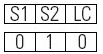 | Sensor 2 should also be blocked.
|
16#9A01 39425 | An illegal input pattern was detected. Sensor 2 and the Light Curtain are blocked and Sensor 1 is cleared. 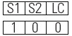 | Sensor 1 should also be blocked.
|
16#9A02 39426 | An illegal input pattern was detected. Sensor 1 and Sensor 2 are cleared and the Light Curtain is blocked. 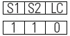 | The Light Curtain should not be blocked when Sensors 1 and 2 are clear.
|
Muting Sequence Faults
Fault Code | Description | Fault Code | Description |
|---|---|---|---|
16#9900 39168 | An illegal muting sequence was detected when Sensor 1, Sensor 2, and the Light Curtain are simultaneously blocked in step 1. 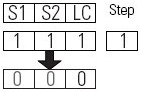 | 16#9901 39169 | An illegal muting sequence was detected while the S1S2-LC Minimum timer is timing and the Light Curtain becomes blocked in step 2. 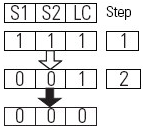 |
16#9902 39170 | An illegal muting sequence was detected after the S1S2-LC Minimum Time expires and Sensor 1 and Sensor 2 are simultaneously cleared in step 2. 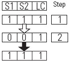 | 16#9903 39171 | An illegal muting sequence was detected when Sensor 1, Sensor 2, and the Light Curtain are simultaneously cleared in step 3. 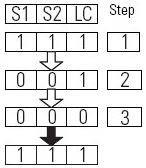 |
16#9904 39172 | An illegal muting sequence was detected when Sensor 1 and Sensor 2 became inconsistent while the Light Curtain was blocked in step 4. 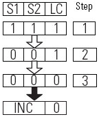 | 16#9905 39173 | An illegal muting sequence was detected while the LC-S1S2 Minimum timer is timing and Sensor 1 and Sensor 2 are cleared in step 4. 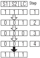 |
16#9906 39174 | An illegal muting sequence was detected while the LC-S1S2 Minimum timer is timing and Sensor 1 and Sensor 2 become inconsistent in step 4.  | 16#9907 39175 | An illegal muting sequence was detected while the S1S2 Discrepancy timer is timing in step 2 (a tolerated sequence) when Sensor 1, Sensor 2, and the light curtain are simultaneously blocked. 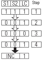 |
To correct an invalid sequence fault, check the alignment of the sensors with regard to the material being moved and the system timing and then reset the fault.
Correcting Invalid Sequence Faults
Fault Code | Description | Corrective Action |
|---|---|---|
16#9000 36864 | The Light Curtain was muted for longer than the configured Maximum Mute Time. | The Maximum Mute Time parameter is set too short or there is an anomaly with the sensors. |
16#9810 38928 | Too much time has elapsed between Sensor 1 and Sensor 2 becoming consistent. | The S1S2 Discrepancy Time parameter is set too short or there is an anomaly with the sensors. |
16#9811 38929 | Too much time has elapsed between Sensor 1 and Sensor 2 being blocked and the Light Curtain being blocked. | The S1S2-LC Maximum Time parameter is set too short or there is an anomaly with the sensors. |
16#9812 38930 | Too much time has elapsed between the Light Curtain being cleared and Sensor 1 and Sensor 2 being cleared. |
Diagnostic Codes
The diagnostic codes are listed in hexadecimal format followed by decimal format.
Diagnostic Code | Description | Corrective Action |
|---|---|---|
0 | No fault. | None |
16#01 1 | The Muting Lamp Status input is OFF (0). |
|
16#05 5 | The Reset input is held ON (1). | Set the Reset input to OFF (0). |
16#20 32 | The Input Status input was OFF (0) when the instruction started. | Check the I/O module connection or the logic used to source input status. |
Affects Math Status Flags
No
Major / Minor Faults
None specific to this instruction. See
Index Through Arrays
for array-indexing faults.Execution
Condition/State | Action Taken |
|---|---|
Prescan | Same as Rung-condition-in is false. |
Rung-condition-in is false | The .O1, .ML, .CA and .FP are cleared to false. |
Rung-condition-in is true | The instruction executes as described in the Normal Operation section. |
Postscan | Same as Rung-condition-in is false. |
Provide Feedback