Resolver Speed Compensation - 1756-PLS
The 1756-PLS module can compensate ON and OFF positions for the speed at which a resolver is turning. Speed compensation allows the module to turn outputs ON and OFF at correct times so that the equipment connected to the 1756-PLS module accurately works at any machine speed.
These factors affect how the module compensates for the speed of the resolver:
- Lead Speed - Distance and RPM - affects ON position
- Trail Speed - Distance and RPM - affects OFF position
The graphic shows limit switch low-high limit Setpoints and, below it, low-high limit Setpoints after they have been adjusted by speed compensation on the 1756-PLS module. Notice that the outputs actually turn ON and OFF before the original Setpoints because of the resolver speed.
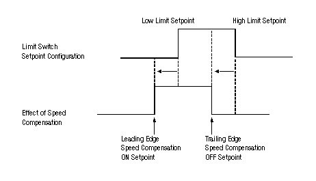
The amount of time the outputs are advanced is the same regardless of speed. The outputs are advanced a larger distance when going faster so that they rotate on 20ms before 75 degrees.
Lead Speed Distance and RPM
The LeadSpeedDistance member sets the distance (in engineering units) to advance the beginning of an output setpoint window for speed compensation.
This parameter must be configured in conjunction with the LeadSpeedRPM member. The LeadSpeedRPM member sets the speed at which a resolver must be turning to compensate by the LeadSpeedDistance member. LeadSpeedDistance is applied proportionally to the actual RPM and LeadSpeedRPM.
For example, you may configure the 1756-PLS module with a LeadSpeedDistance of 10 and a LeadSpeed RPM of 5. For every 5 RPM, the setpoint window will advance 10. An RPM of 20 will cause the module to advance the beginning of the setpoint window 40. An RPM of 13 will cause the module to advance the beginning of the setpoint window 26.
If you use a distance value of 0, the module will not use speed compensation.
Trail Speed Distance and RPM
The TrailSpeedDistance and RPM are the same as LeadSpeed, but affect the position of the ON to OFF transition.
Configuring Speed Compensation for a Specific Lead Time
If the 1756-PLS module controls a device with a known lag time, it may be more convenient to configure the speed compensation using time units. Use the formula to convert the lag time to equivalent distance and RPM:
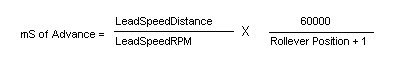
For example, if:
- Rollover Counts = 4095
- Rollover Position = 4095
- LeadSpeedDistance = 1
- LeadSpeedRPM =1
These parameters cause the Limit Switch to turn ON 14.6mS before reaching the programmed setpoint angle.
The equation determines speed compensation for applications using degrees as the engineering units.
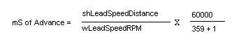
Using this equation, if:
- RolloverCounts = 4095
- RolloverPosition = 359
- LeadSpeedDistance = 1
- LeadSpeedRPM = 1
The limit switch turns ON 166ms before reaching the programmed setpoint angle.
Determining Lead Speed Distance and RPM for a Desired Lead Time
You may want your 1756-PLS module application to use a specific lead time. Use the worksheet to calculate the appropriate LeadSpeedDistance and LeadSpeedRPM.
The worksheet uses a LeadSpeedRPM of 1000.
- Desired Lead Time: ___________ (in ms)
- RolloverPosition + 1: ___________
- LeadSpeedRPM: 1000
- Use the equation to calculate LeadSpeedDistance:
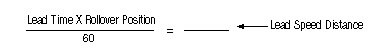
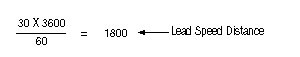
For example, using the worksheet and equation to calculate a LeadSpeedDistance when you want a Lead Time of 30ms and you are measuring position in 0.1 degree units.
- Desired Lead Time: 30ms
- Rollover Position + 1: 3599 + 1 = 3600
- Lead Speed RPM: 1000
- Use the following equation to calculate LeadSpeedDistance:
RPM Filter
The RPM filter adjusts how quickly the RPM reported by the module, and used internally for speed compensation, tracks the actual RPM. Typically, the RPM filter should be configured so the 1756-PLS module RPM closely follows any speed changes.
You can configure the RPM filter so that minor changes in the resolver’s RPM are not reported. In this case, the average RPM rate is reported.
For example, the resolver may be connected to a motor that oscillates between 100 and 102 RPM approximately every 0.5 seconds. The RPMFilter member, if configured to lag behind the actual RPM when reporting speeds, may report a resolver RPM of 101. In this case, continued increases in speed, such as RPM values of 103 and 104, will be reported slightly later than they actually occurred.
Use the table to choose a value for the RPMFilter member.
Filter Value: | Effect: |
16#4000 | Reported RPM matches actual RPM closely |
16#8000 | Reported RPM matches actual RPM somewhat closely |
16#C000 | Reported RPM lags actual RPM somewhat |
16#F000 | Reported RPM lags actual RPM by a few seconds |
Provide Feedback