- Studio 5000 Logix Designer
- Tasks, programs, and routines
- Add-On Instructions
- Controller Organizer
- Logical Organizer
- Alarms
- Tag-based alarms
- Tag Editor and Data Monitor
- Configure settings for Tag Editor and Data Monitor
- Equipment phases
- Equipment Sequences
- Equipment Sequence Diagrams
- Ladder Editor
- Structured Text Editor
- Sequential Function Chart Editor
- Define the steps of an SFC process
- PlantPAx instruction properties
- Controller Properties
- Editing Controller Properties
- Controller Security
- Source Protection
- License Source Protection for Routines and Add-On Instructions
- Module Information
- 1756 ControlLogix I/O Modules
- Instruction Set
Configuring a SERCOS analog motion system
Configuring a motion system is a process with many different configuration options. Basic SERCOS motion system setup requires these steps in the Logix Designer application:
Step | Process | Reason |
1. | Add a SERCOS motion module | Identifies the motion module being used to the Logix controller |
2. | Configure module properties | Defines how the module connects to the controller and how data is transferred. |
3. | Add a SERCOS interface drive module to the controller I/O configuration | Establishes the communications channel between the drive module and the controller |
4. | Modify properties for the interface drive | Defines the axes and power settings for the motion module |
5. | Add a motion group | Consolidates the axes into a control set to provide coordinated motion. |
6. | Set the base update rate | Selects the periodic rate (at which the Motion Planner executes motion tasks) to compute the servo commanded position, velocity, and accelerations to be sent to the output modules when executing motion instructions |
7. | Add an axis | An axis is used to define forward and backward motion in one direction. |
8. | Configure a SERCOS motion axis | Configures the individual attribute of the motion axis. |
For the purposes of this quick start, assume this configuration:
- A new controller project with a SERCOS motion module configured
- Linear Displacement Transducer feedback
- Servo axis configurationIMPORTANT: For all modules, use the firmware revision that goes with the firmware revision of your controller. See the release notes for your controller’s firmware.
Add a SERCOS motion module
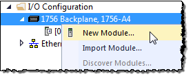
- In theController Organizer, right-click the backplane and chooseNew Module.
- On theSelect Module Typedialog box, choose the module that you want to add.
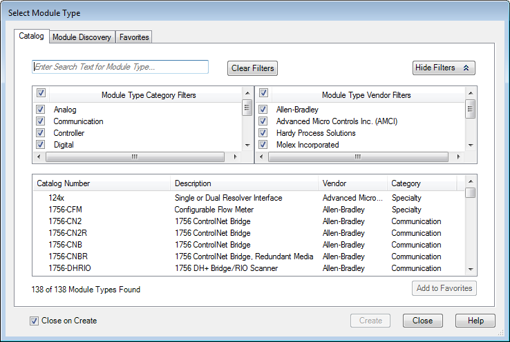
- Select theClose on Createcheck box, and clickCreate.
- On theNew Moduledialog box, in theNamebox, type a name for the module.
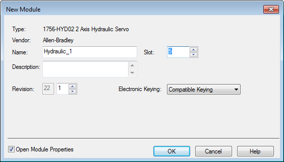
- In theSlotbox, choose the number that corresponds to the physical slot that contains the module.
- (optional) In theDescriptionbox, type a description.
- In theElectronic Keyinglist, choose a keying option of eitherCompatible KeyingorExact Match.WARNING:Disable Keyingshouldneverbe used with motion modules.
- Select theOpen Module Propertiescheck box, and clickOK.
Configure module properties
- If theModule Properties Reportdialog box is not already open, in theController Organizer, double-click the motion module.
- On theModule Properties Reportdialog box, click theConnectiontab.
- Verify that theMajor Fault on Controller If Connection Fails While in Run Modecheck box is clear.
 TIP: Keep this check box clear until you execute the program the first time. If this check box is selected, then a Major Fault is generated when the SERCOS ring attempts to phase up the first time.
 - Click theSERCOS Interfacetab.
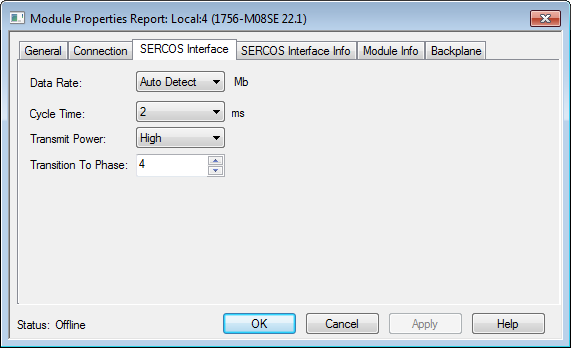
- In theData RateandCycle Timeboxes, choose the baud rate and update rate for the SERCOS ring using the following table as a guide. The data rate and the number of drives associated with the module dictate your minimum cycle time.Baud Rate of DrivesNumber of Drives on the RingType of DrivesCycle Time4 MbpsUp to 2Kinetix 2000Kinetix 6000Kinetix 6200Kinetix 70000.5 msUp to 4—1 msUp to 8—2 ms9…16—No Support8 MbpsUp to 4Kinetix 2000Kinetix 6000Kinetix 6200Kinetix 70000.5 msUp to 8—1 msUp to 16—2 ms
- ClickOK.
Add a SERCOS interface drive module to the controller I/O configuration
The interface module links the controller to the drive.
- In theController Organizer, right-clickSERCOS Networkand chooseNew Module.
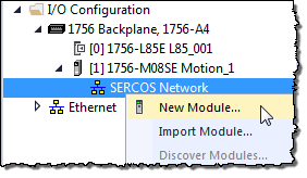
- On theSelect Module Typedialog box, choose the module that you want to add.
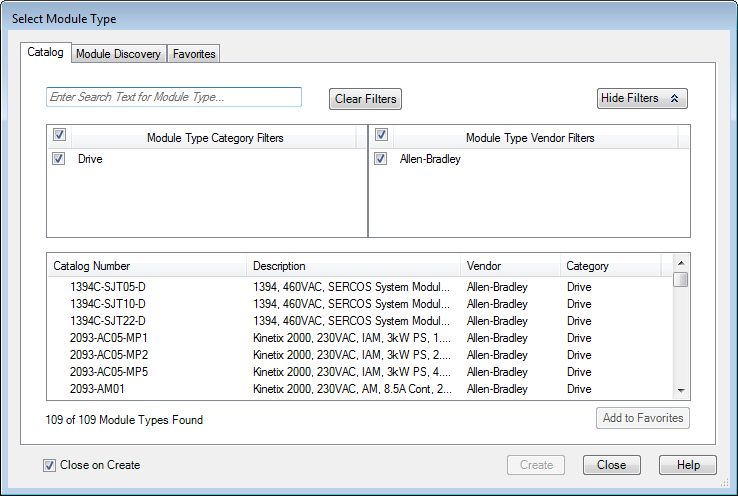
- Select theClose on Createcheck box, and clickCreate.
- On theNew Moduledialog box, in theNamebox, type a name for the interface drive.
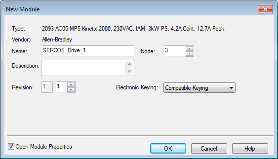
- In theNodebox, choose the SERCOS node number of the interface drive (see the module's rotary switch).
- (optional) In theDescriptionbox, type a description.
- In theRevisionboxes, select the Major Revision and Minor Revision of the module.
- In theElectronic Keyinglist, choose a keying option of eitherCompatible KeyingorExact Match.WARNING:WARNING: Disable Keyingshouldneverbe used with motion modules.
- Select theOpen Module Propertiescheck box, and clickOK.
Modify properties for the interface drive
- If theModule Properties Reportdialog box is not already open, in theController Organizer, double-click the interface drive.
- On theModule Properties Reportdialog box, click theAssociated Axestab.
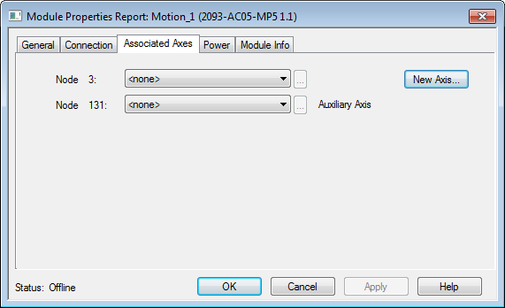
- ClickNew Axisto create an AXIS_SERVO tag to associate to one of the nodes.
- On theNew Tagdialog box, in theNamebox, type a name for the axis tag.
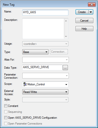
- ClickCreate.
- (optional) Repeat steps 3 through 5 if an additional axis is required.
- On theModule Properties Reportdialog box, in theNode(Number) box, choose an AXIS_SERVO_DRIVE tag to associate with the drive’s node.
- (optional) In the secondNode(Number) box, choose an axis.
- Click thePowertab.
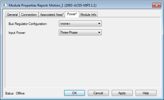
- In theBus Regulator Configurationbox, choose the catalog number that describes the bus regulator device used by the drive module. Depending upon the drive you have selected, one or more of the bus regulator IDs may be available.IMPORTANT: This setting does not apply to the 8720MC drive, the Ultra3000 SERCOS drive, or Kinetix 6200 Integrated Drive Motor (IDM) drive. For those drives,noneis the only available option.
- If you are configuring a Kinetix 2000 230-volt drive, in theInput Powerbox, chooseSingle-PhaseorThree-Phase.
- If you are configuring an IDM Power Interface Module (IPIM) or IDM module, in theAdditional Bus Capacitancebox, choose the additional bus capacitance that is required. This parameter is only valid if an axis is associated with the Kinetix 6000 and Kinetix 6200 IAM module. When an axis is initially associated to the IAM, this parameter shows the default value and is enabled. If a valid value is set in the associated axis, and the axis is not associated to the IAM, this parameter is reset to the default value and cannot be changed until an axis is associated to the IAM.
- ClickOK.
Add a motion group
Motion groups collect axes together so that their motion can be controlled as a single unit.
IMPORTANT:
Only one motion group can be created for each project.
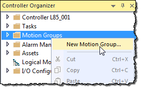
- In theController Organizer, right-clickMotion Groupsand chooseNew Motion Group.
- On theNew Tagdialog box, in theNamebox, type a name for the motion group.
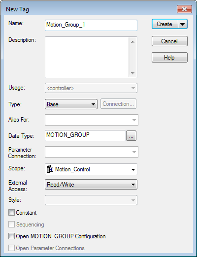
- (optional) In theDescriptionbox, type a description.
- ClickCreate.
Set the base update rate
The Base Update Period (also known as the Coarse Update Period) is how often the motion planner runs. The motion planner is the part of the controller that handles position and velocity information for the axes. When the motion planner runs, it interrupts most other tasks regardless of their priority.
- In theController Organizer, double-click the motion group.
- Click theAttributetab.
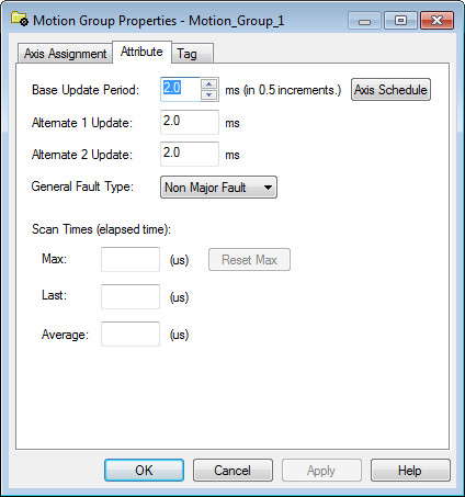
- In theBase Update Periodbox, choose the update period. The valid values range from0.5to32, in 0.5 increments.Guidelines for the Base Update Period.GuidelineDescriptionNumber of Axes1756-L 6xcontroller 4 axes/ms1756-L7xcontroller8 axes/msSave Controller’s TimeLeave at least half the controller’s time for the scan of all your code.Base Update Period and SERCOS modulesSet the Base Update Period to a multiple of the cycle time of the motion module.Example: If the cycle time is 2 ms, set the Base Update Period to 8 ms, 10 ms, 12ms, and so on.Base Update Period and Analog modulesSet the Base Update Period to:
- at least 3 times the servo update period of the motion module.
- a multiple of the servo update period of the motion module.
- In theGeneral Fault Typelist, chooseNon Major Fault.
- ClickOK.
Add an axis
Add an axis for each of your drives.
- In theController Organizer, right-click the motion group and chooseNew Axis.
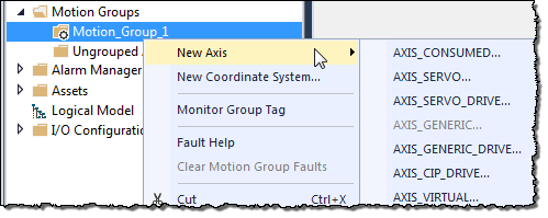
- Choose the data type.
- For these motion modules, chooseAXIS_SERVO_DRIVE.
- 1756-M03SE
- 1756-M08SE
- 1756-M16SE
- 1768-M04SE
- To use a virtual configuration (no hardware), chooseAXIS_VIRTUAL.
- On theNew Tagdialog box, in theNamebox, type a name for the axis.
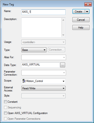
- (optional) In theDescriptionbox, type a description for the axis.
- ClickCreate.
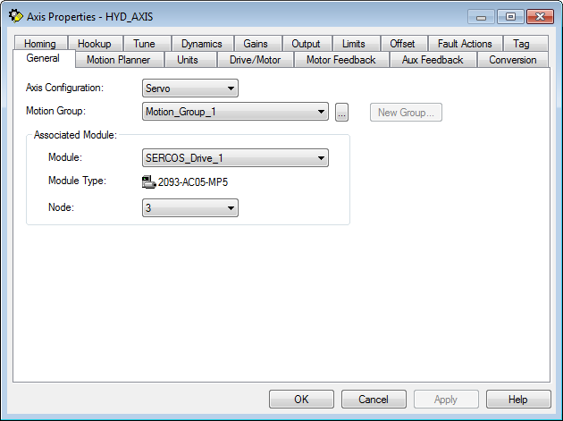
Configure a SERCOS motion axis
After the axis is created, configure the axis of a SERCOS interface drive. The steps may differ depending on the type of drive you are configuring.
- In theController Organizer, double-click the axis.
- On theGeneraltab, verify that the assigned motion group and module information is correct. Make any needed changes.
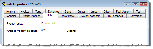
- Click theUnitstab, and in thePosition UnitsandAverage Velocity Timebaseboxes, enter the values.
- Click theDrive/Motortab.
- ClickChange Catalog, and on theChange Catalog Numberdialog box, choose the related motor catalog numbers, and clickOK.
 The following conditions apply for the Integrated Drive Motor (IDM).
- TheAmplifier Catalog Numberappears dimmed and cannot be edited when the axis is associated to an IDM.
- TheMotor Catalog Numberis automatically set to the catalog number of the only motor available from the Motion Database for the IDM module when it is associated to the axis.
- The Catalog Number for the IDM appears dimmed and is read-only. It is automatically set to the compatible motor from the motion database for each IDM.
- An IDM does not support Auxiliary Axis loop configurations. When theAxis Configurationbox on theGeneraltab is set toServo, the selections forLoop Configurationfor the IDM are:
- Position Servo
- Dual Command Servo (does not use the Auxiliary Port)
- Velocity Servo
- Torque ServoWhen theAxis Configurationbox on theGeneraltab is set toFeedback Only, the selection forLoop Configurationfor the IDM isMotor Feedback Only.
- The following are real-time attributes for the IDM.
- Position Command
- Position Feedback
- Position Error
- Position Int. Error
- Velocity Command
- Velocity Feedback
- Velocity Error
- Velocity Int. Error
- Accel Command
- Accel Feedback
- Marker Distance
- Torque Command
- Torque Feedback
- Positive Dynamic Torque Limit
- Negative Dynamic Torque Limit
- Motor Capacity
- Drive Capacity
- Power Capacity
- Bus Regulator Capacity
- Motor Electrical Angle
- Torque Limit Source
- DC Bus Voltage
- In theDrive Resolutionbox, type the resolution, and then in theDrive Counts /box, select the units.
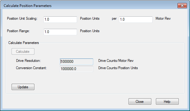
- ClickCalculate.
- On theCalculate Position Parametersdialog box, clickCalculate, review the values and adjust as needed until you have the desired calculated values, then clickUpdateandClose.
- Click theHomingtab, and in theModebox, choose the homing mode.
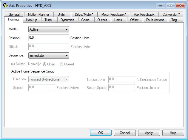
- In thePositionbox, type the position units.
- In theSequencebox, choose the sequence type.
- For all sequence types exceptIntermediate, in theDescriptionbox, choose the active home sequence type, and then in theSpeedandReturn Speedboxes, set the homing speeds.
- ClickOKto apply the changes.
Provide Feedback