- Studio 5000 Logix Designer
- Tasks, programs, and routines
- Add-On Instructions
- Controller Organizer
- Logical Organizer
- Alarms
- Tag-based alarms
- Tag Editor and Data Monitor
- Configure settings for Tag Editor and Data Monitor
- Equipment phases
- Equipment Sequences
- Equipment Sequence Diagrams
- Ladder Editor
- Structured Text Editor
- Sequential Function Chart Editor
- Define the steps of an SFC process
- PlantPAx instruction properties
- Controller Properties
- Editing Controller Properties
- Controller Security
- Source Protection
- License Source Protection for Routines and Add-On Instructions
- Module Information
- 1756 ControlLogix I/O Modules
- Instruction Set
C
calibration
The process of comparing an instrument or device with a standard to verify its accuracy. It also includes making adjustments to meet the standard, or devising a corrected scale.
cam
A set of ordered points without coefficients. The type of connecting segment is included in this definition.
cam element
Includes a cam point and the segment immediately to the right of that point.
For the output cam editor, a cam element includes the cam left and cam right positions, and the segment between them.
cam point
A position within a cam profile determined by the coordinates of the master and slave.
cam profile
A representation of non-linear motion (that is, a motion profile) which includes a start point, end point, and all points and segments in between. A cam profile is represented by an array of cam elements. Click on the graphic below for more information on individual parts of the cam profile.
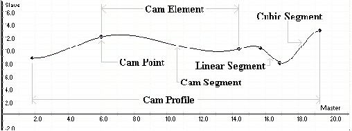
cam segment
The path from one cam point to the next cam point.
caret
A colored rectangle that indicates the current working location within the ladder routine in the ladder editor.
TIP:
The color of the rectangle is determined by the settings you have chosen in the Windows Control Panel. The color you have chosen as the Selection color or Selected Text color is the color of the rectangle that will be used as the caret.
cascade loop
The attachment of output from one PID loop or instruction to the input of another PID loop or instruction. This allows for different feedback to be introduced at different levels in the control loop.
central processing unit (CPU)
The decision-making and data storage section of a programmable controller.
Change Active Step
The
Change Active Step
command is a way to change the set of active elements within an executing sequence. The sequence must be in Manual
mode so transitions will not fire and change the set of steps that are active. You can choose steps to activate and deactivate.chassis
A hardware assembly that houses devices such as I/O modules, adapter modules, processor modules, and power supplies.
chassis type
A supported chassis type from the list. Each entry in the list consists of the catalog number of the chassis, as well as a brief description, including the number of slots. The chassis type cannot be changed when online.
CIP object
An object that conforms to the CIP message protocol. Peer controller access to a CIP object requires the use of the CIP Generic Messaging type within a message instruction. Local access to the CIP objects within a ControlLogix system is done via the GSV/SSV instructions.
clear
Defines the status of bits (Booleans) and values (non-Booleans).
Clear indicates that the bit is cleared to 0 (Off), and all the bits in a value are cleared to 0.
Clear-to-Send (CTS)
A signal that tells the transmitting device to start transmitting data.
closed-loop system
A control system involving one or more feedback control loops, which combine functions of controlled signals and commands to keep the relationship stable between the two.
coarse rate
A type of rate that selects the periodic rate (at which the motion task executes) to compute the servo commanded position, velocity, and accelerations to be sent to the output modules when executing motion instructions.
TIP:
If the coarse rate is too small, the AC processor may not have time to execute non-motion related ladder logic. As a general rule, one millisecond per axis is required by the motion task in order to allow the processor reasonable execution time.
To calculate the coarse rate (or coarse update period) for the number of axes in your application, use the following formula:
2 *(Baseline task time + [Actions for axis 1 + Actions for axis 2 . . . + Actions for axis n]) = Coarse Update period |
You must then divide the result of this calculation by 1000 and round it to the nearest millisecond.
cold junction sensor (CJS)
A thermistor that measures the ambient temperature of the thermocouple wire connected to the screw terminals. The measured temperature is used to properly compensate for the cold junction thermoelectric effect present between the thermocouple wiring and the terminals. The CJS may be mounted on the terminal block, between terminals 10 and 14, or positioned remotely in a Remote Termination Block (RTB).
comma-separated values (CSV) file
A file format in which fields are delimited by commas. This format is supported by several products, including Microsoft Excel software, RSLogix 5 software, RSLogix 500 software, and Logix Designer software. Logix Designer software can export a CSV file that contains an ASCII representation of tag information. Furthermore, Logix Designer software can import from a CSV file and add or modify tag information to an open project.
The file extension for this format must be .CSV; if you change the extension using a tool like the Windows Explorer, Logix Designer software does not import the file.
command position
The position that is used by the control loops to move the feedback element to match.
command velocity
The velocity that is used by the control loops to move the feedback element to match.
comment
The user text associated with various items in the project that are used to explain the use/purpose of that item. Most items in a Logix Designer project support user comments. This includes Tasks, Programs, Routines, Rungs, Tags, User Defined Structures, User Defined Structure Members and Modules. Comments do not affect the operation of the users program in any way.
Common Industrial Protocol (CIP)
The Common Industrial Protocol (CIP) is an industrial protocol for industrial automation applications supported by ODVA. Previously known as Control and Information Protocol, CIP defines messages and services for the collection of manufacturing automation applications – control, safety, synchronization, motion, configuration, and information. It is used in EtherNet/IP, DeviceNet, CompoNet, and ControlNet. Extensions to CIP are CIP Safety, CIP Motion, CIP Security, and CIP Sync.
communication fault behavior
Determines how module outputs behave when the connection between the controller and the module is broken, but the module's outputs remain active.
communication format
Defines how an I/O module or communication card communicates with the controller. Choosing a communication format defines:
- which configuration pages will be available, and
- the tag structure and configuration method
TIP:
For I/O modules, once you create the module, you cannot change the communication format. To change configuration, you must delete and recreate the module. For communication cards, the communication format is configurable after creation.
Compatible Module
Compatible Module lets the installed device accept the key of the device that is defined in the project when the installed device can emulate the defined device. With Compatible Module, typically replace a device with another device with these characteristics:
- Same catalog number
- Same or higher Major Revision
- Minor Revision as follows:
- If the Major Revision is the same, the Minor Revision must be the same or higher.If the Major Revision is higher, the Minor Revision can be any number.
complementary I/O addressing
An I/O configuration in which an input module in one slot location and an output module in another slot location are given the same location address. This is considered complementary because one uses only the input image, and the other uses only the output image.
complementary output
An output circuit with dual output switching devices such that when one is On, the other is Off.
connected state
A limited Online state where the workstation has a connection open to the controller, but the image in the controller is not correlated with the open project file. This is the state of the "Project Not Correlated" dialog. The online functionality in this state is limited to reading certain controller status information, and changing the controller mode (Run, Program, or Test).
connection
The link between networks and devices.
connection fault
A failure in the controller’s connection to a module. Data is no longer transferred between the controller and the module when a connection fault occurs. If the controller is configured to fault on failure of the connection, a controller fault occurs.
Consumed tag
A tag whose value comes from a remote controller. The local controller is the consumer, and the remote controller is the producer. Consumed tags are always at controller scope.
continuous task
A task that runs continuously (that is, in the background), from top to bottom, through all its assigned programs, unless interrupted by another task. All CPU time not allocated to other operations (for example, motion, communications, and periodic or event tasks) is used to execute the programs within the continuous task. Once the task completes a full execution scan, an output update is triggered and the scan immediately starts over at the top.
TIP:
A project does not require a continuous task. However, you can only configure one continuous task per project.
CONTROL
A structure data type containing status and control information for instructions that require a control block, such as file instructions.
control parameter
A kind of input parameter that generally specifies a control value for a piece of equipment such as a temperature for an oven or the agitation time for a mixer. The preferred method for defining a control parameter within an Equipment Sequence is to use an input program parameter.
control variable (CV)
A variable representing the computed output or value used to control the process in a feedback control loop.
ControlBus
The backplane used by the 1756 chassis.
controller
A device that controls machines or processes elements (for example, a programmable controller or relay panel).
controller fault
A trapped condition where normal or correct operation of the controller may be interrupted. The condition may be a program fault or another condition. Faults are categorized by severity into major faults and minor faults. Faults can be trapped by a fault routine or a controller fault handler program to take corrective action.
controller fault handler program
A program that can be configured to handle major faults. All program faults that are not handled by a fault routine execute this program (as well as any other kind of major fault).
controller file
See project file.
Controller Organizer
A graphical representation of the contents of your project. This window consists of a hierarchical tree of the folders, files and links that contain all of the information about the programs and data in the current project. The Controller Organizer is a Tool Window that you can resize, undock, dock, and move.
controller overhead
An internal portion of the operating cycle used for housekeeping and setup purposes.
controller scope
The data accessible from anywhere in the controller. The controller contains a collection of tags that can be referenced by the routines and aliases in any program, as well as other aliases in the controller scope.
controller tag
A tag at controller scope.
ControlNet network
An open control network that uses the producer/consumer model to combine the functionality of an I/O network and a peer-to-peer network, while providing high-speed performance for both functions.
coordinated system time (CST)
A timer value that is kept synchronized for all modules within a single ControlBus chassis. Date timestamped with CST data, from modules within a single ControlBus chassis, can safely be compared to determine the relative time between data samples.
correlated
A correlated project file is a file that matches the contents of a controller, to a sufficient extent, to enable the programming software to go online.
COUNTER
A structure data type that contains status and control information for counter instructions.
counter
A device that counts the occurrence of an event.
counts
The smallest unit by which the feedback element measures position whether linear or angular.
creatable module
Indicates that the Module Type is part of the list of modules and a profile for that module type can be created and configured in Logix Designer under the current circumstances. An example of a given module type that is not a creatable module would be if Logix Designer is online and the module type is in the list of modules but cannot be created online.
critical module
A control critical module is one which, if it is removed while the control program is running, will cause a fault in one or more of the remaining modules in the chassis.
crossload
To update information on a secondary control chassis by performing a data transfer from a primary control chassis.
cubic segment
A smooth curve between two or more cam points.
current communications path
The current path is displayed in the Online bar, and you can change it using the Who Active dialog. This is the path that the Logix Designer application uses when you choose Go Online, Upload, or Download from the menu, and it appears in the Current Path field when you open the Who Active dialog.
The current path is written to any projects you create; use the Who Active dialog to change the path in your project.
When you open a project, its communication path becomes the current path.
cyclic redundancy check (CRC)
A Cyclic Redundancy Check (CRC) is an error checking technique used by computers.
Provide Feedback