| Interface |
3 Digital
|
|---|
| With approval according to UL |
False
|
|---|---|
| North American temperature code |
T4A
|
| IEC temperature code |
T4
|
| With detachable clamps |
True
|
|---|---|
| Enclosure type rating |
None (open-style)
|
| Vibration |
2.0 G @ 10…500 Hz
|
| Shock |
Opsal: 15 G
|
| Width |
94 mm
|
| Height |
97 mm
|
| Depth |
94 mm
|
| Rail mounting possible |
True
|
| Voltage type for actuating |
DC
|
|---|---|
| Rated control supply voltage at DC |
24 V
|
| Model |
Expansion device
|
| Type of electric connection |
Plug-in connection
|
| Wire type |
Signal connections: shielded, Power and relay connections: unshielded
|
| Wiring category |
2 - on relay, power, and signal ports, 3 - on serial ports, 2 - on XM bus ports
|
| Power dissipation, max |
2.9 W
|
| Surrounding air temperature, max |
65 °C
|
|---|---|
| Operating temperature |
-20 °C
|
| Emissions |
Class A
|
| Relative humidity |
5...95% noncondensing
|
| ESD immunity |
4 kV contact discharges, 8 kV air discharges
|
| EFT/B immunity |
±2kV @ 5kHz on power ports, ±1kV @ 5kHz on relay and signal ports, ±1kV @ 5kHz on XM bus port
|
| Surge transient immunity |
±1 kV line-earth(CM) on relay ports, ±1 kV line-earth(CM) on signal ports, ±1 kV line-earth(CM) on XM bus port
|
| Conformal coating |
All printed circuit boards are conformally coated in accordance with IPC-A-610C
|
| Radiated RF immunity |
10 V/m with 1 kHz sine-wave 80% AM from 80...2000 MHz, 10 V/m with 200 Hz 50% Pulse 100% AM @ 900 MHz, 10 V/m with 200 Hz 50% Pulse 100% AM @ 1890 MHz, 3 V/m with 1 kHz sine-wave 80% AM from 2000...2700 MHz
|
| Storage temperature |
-40 °C
|
| Nonoperating temperature |
-40 °C
|
| Conducted RF immunity |
10V rms with 1 kHz sine-wave 80% AM from 150 kHz...80 MHz
|
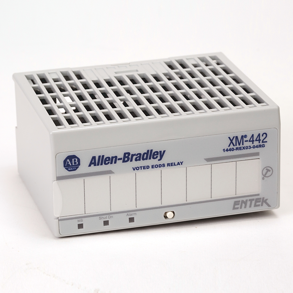
| Status indicator |
Module power - red/green, Shutdown relay - red, Alarm relay - red
|
|---|
| Reset |
Local reset switch on top of module, Remote reset switch that is wired to terminal base
|
|---|---|
| Failsafe |
Normally energized
|
| Logic |
Two-out-of-three, One-out-of-three
|
| Number |
Four relays, two sets of contacts each - DPDT (2 Form C)
|
| Contacts |
250V AC @ 50/60Hz @ 3 A resistive, 150V DC @ 1.6A resistive
|
| Activation |
Low logic level (<0.8V) on the overspeed/circuit fault inputs
|
| Latching |
The shutdown and alarm relays latch when the conditions that activate them are met
|
| Heat production, max |
2.9 W
|
|---|---|
| Voltage and current ratings |
Supply: 24V DC @ 0.2A maximum, Class 2/SELV, Relay: 250V AC @ 50/60Hz, 3 A Res, 150V DC @ 1.6A Res
|
| Host communication |
The XM-442 module communicates to the speed modules connected to it only via the three digital inputs on the front of the terminal base. Power and communication pass through the side connector of the terminal base but are not used by the XM-442 module
|
|---|
| Type | Resource | Publication |
|---|---|---|
| General | Product Cutsheet | -- |
| Technical Data | 1440-td001_-en-p | 1440-TD001 |
Looking for more documentation?
Find curated technical documentation for this product in the Technical Documentation Center, or search our full Literature Library.
Search the Literature Library
- China CCC
- UKCA DOC
- ATEX
This product was certified with the above certifications as of 2025-11-17. Products sold before or after this date might carry different certifications. Please review the product label to check for the certifications your specific product carries.
Looking for more Technotes?
Find questions and answers from Rockwell Automation technical experts for this product in our Knowledgebase.
Search Knowledgebase
Technical Specifications
| Interface |
3 Digital
|
|---|
| With approval according to UL |
False
|
|---|---|
| North American temperature code |
T4A
|
| IEC temperature code |
T4
|
| With detachable clamps |
True
|
|---|---|
| Enclosure type rating |
None (open-style)
|
| Vibration |
2.0 G @ 10…500 Hz
|
| Shock |
Opsal: 15 G
|
| Width |
94 mm
|
| Height |
97 mm
|
| Depth |
94 mm
|
| Rail mounting possible |
True
|
| Voltage type for actuating |
DC
|
|---|---|
| Rated control supply voltage at DC |
24 V
|
| Model |
Expansion device
|
| Type of electric connection |
Plug-in connection
|
| Wire type |
Signal connections: shielded, Power and relay connections: unshielded
|
| Wiring category |
2 - on relay, power, and signal ports, 3 - on serial ports, 2 - on XM bus ports
|
| Power dissipation, max |
2.9 W
|
| Surrounding air temperature, max |
65 °C
|
|---|---|
| Operating temperature |
-20 °C
|
| Emissions |
Class A
|
| Relative humidity |
5...95% noncondensing
|
| ESD immunity |
4 kV contact discharges, 8 kV air discharges
|
| EFT/B immunity |
±2kV @ 5kHz on power ports, ±1kV @ 5kHz on relay and signal ports, ±1kV @ 5kHz on XM bus port
|
| Surge transient immunity |
±1 kV line-earth(CM) on relay ports, ±1 kV line-earth(CM) on signal ports, ±1 kV line-earth(CM) on XM bus port
|
| Conformal coating |
All printed circuit boards are conformally coated in accordance with IPC-A-610C
|
| Radiated RF immunity |
10 V/m with 1 kHz sine-wave 80% AM from 80...2000 MHz, 10 V/m with 200 Hz 50% Pulse 100% AM @ 900 MHz, 10 V/m with 200 Hz 50% Pulse 100% AM @ 1890 MHz, 3 V/m with 1 kHz sine-wave 80% AM from 2000...2700 MHz
|
| Storage temperature |
-40 °C
|
| Nonoperating temperature |
-40 °C
|
| Conducted RF immunity |
10V rms with 1 kHz sine-wave 80% AM from 150 kHz...80 MHz
|
| Status indicator |
Module power - red/green, Shutdown relay - red, Alarm relay - red
|
|---|
| Reset |
Local reset switch on top of module, Remote reset switch that is wired to terminal base
|
|---|---|
| Failsafe |
Normally energized
|
| Logic |
Two-out-of-three, One-out-of-three
|
| Number |
Four relays, two sets of contacts each - DPDT (2 Form C)
|
| Contacts |
250V AC @ 50/60Hz @ 3 A resistive, 150V DC @ 1.6A resistive
|
| Activation |
Low logic level (<0.8V) on the overspeed/circuit fault inputs
|
| Latching |
The shutdown and alarm relays latch when the conditions that activate them are met
|
| Heat production, max |
2.9 W
|
|---|---|
| Voltage and current ratings |
Supply: 24V DC @ 0.2A maximum, Class 2/SELV, Relay: 250V AC @ 50/60Hz, 3 A Res, 150V DC @ 1.6A Res
|
| Host communication |
The XM-442 module communicates to the speed modules connected to it only via the three digital inputs on the front of the terminal base. Power and communication pass through the side connector of the terminal base but are not used by the XM-442 module
|
|---|
Documents
|
Product Cutsheet
General
-- |
|
1440-td001_-en-p
Technical Data
1440-TD001 |
| Type | Resource | Publication |
|---|---|---|
| General | Product Cutsheet | -- |
| Technical Data | 1440-td001_-en-p | 1440-TD001 |
Looking for more documentation?
Find curated technical documentation for this product in the Technical Documentation Center, or search our full Literature Library.
Search the Literature Library
Certifications
- China CCC
- UKCA DOC
- ATEX
This product was certified with the above certifications as of 2025-11-17. Products sold before or after this date might carry different certifications. Please review the product label to check for the certifications your specific product carries.
Alternative Products
Technotes
Looking for more Technotes?
Find questions and answers from Rockwell Automation technical experts for this product in our Knowledgebase.
Search Knowledgebase
Loading

Copyright ©2025 Rockwell Automation, Inc.