1768-cnb
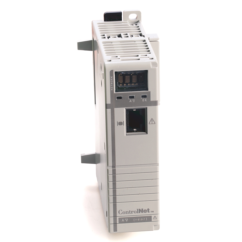
CompactLogix L4X ControlNet Module
Rockwell Automation announces that as of January 31, 2020, the CompactLogix L4X ControlNet Module will be discontinued and no longer available for sale. Customers are encouraged to remove references to the affected product(s)
Discontinued Date:
January 31, 2020
Replacement Category:
Engineering Replacement
| Communication |
ControlNet
|
|---|---|
| Connection Cables |
1 m Tap
|
| Interface |
1 ControlNet BNC,1 ControlNet RJ45
|
| Isolation |
30V (continuous), functional insulation type, Tested at 710V DC @ 60s, ControlNet port to system
|
| Number Of Channels |
1
|
| Number of HW-interfaces industrial Ethernet |
1
|
|---|---|
| Suitable for safety functions |
False
|
| With optical interface |
False
|
| Supporting protocol for TCP/IP |
False
|
| Supporting protocol for DeviceNet |
False
|
| Supporting protocol for other bus systems |
False
|
| Redundancy |
False
|
| IO link master |
False
|
| Supporting protocol for DeviceNet Safety |
False
|
| Supporting protocol for EtherNet/IP |
False
|
| Type of data transmission |
Other
|
| Logix communication connections |
48
|
| Power dissipation |
5.14 W
|
| Thermal dissipation |
17.5 btu/h
|
| Configuration |
Standard
|
| Enclosure type rating |
None (open-style)
|
| Number of nodes, max |
99 nodes
|
| Current draw |
1A @ 5.2V DC
|
| ControlNet cable |
Quad shield RG6 coaxial cable
|
| Ports |
1 ControlNet BNC, 1 ControlNet RJ45
|
| Wire category |
2 - on communication ports
|
| Isolation voltage |
30V (continuous), functional insulation type, ControlNet to backplane, No isolation between NAP and Backplane, Type tested at 500V AC @ 60s, ControlNet network to system
|
| Supporting protocol for LON |
False
|
| Supporting protocol for ASI |
False
|
| Supporting protocol for PROFIBUS |
False
|
| Supporting protocol for CAN |
False
|
| Supporting protocol for INTERBUS |
False
|
| Supporting protocol for KNX |
False
|
| Supporting protocol for Modbus |
False
|
| Supporting protocol for Data-Highway |
False
|
| Supporting protocol for SUCONET |
False
|
| With potential separation |
False
|
| Supporting protocol for SERCOS |
False
|
| Supporting protocol for INTERBUS-Safety |
False
|
| Radio standard Bluetooth |
False
|
| Radio standard Wi-Fi 802.11 |
False
|
| Supporting protocol for AS-Interface Safety at Work |
False
|
| Supporting protocol for Foundation Fieldbus |
False
|
| Supporting protocol for PROFINET CBA |
False
|
| Supporting protocol for PROFINET IO |
False
|
| Supporting protocol for PROFIsafe |
False
|
| Supporting protocol for SafetyBUS p |
False
|
| Radio standard GPRS |
False
|
| Radio standard GSM |
False
|
| Radio standard UMTS |
False
|
| Slot width |
1
|
| ControlNet communication rate |
5 mbit/s
|
| Width |
56.7 mm
|
|---|---|
| Height |
132 mm
|
| Depth |
105.1 mm
|
| Weight, approx |
0.26 kg
|
| Module location |
DIN rail or panel mount
|
| Mounting screw torque |
1.16 Nm (10 in-lb) - use M4 or #8 screws
|
| Surrounding air temperature, max |
60 °C
|
|---|---|
| Emissions |
CISPR 11 (IEC 61000-6-4): Class A
|
| Vibration |
5 G @ 10...500 Hz
|
| ESD immunity |
6 kV contact discharges, 8 kV air discharges
|
| EFT/B immunity |
±2kV @ 5kHz on communications ports
|
| Relative humidity |
5...95% noncondensing
|
| Shock |
Operating: 30 G
|
| Conducted RF immunity |
10V rms with 1 kHz sine-wave 80% AM from 150 kHz...80 MHz
|
| Surge transient immunity |
±1 kV line-earth(CM) on communications ports
|
| Nonoperating temperature |
-40 to 85 °C
|
| Operating temperature |
0 to 60 °C
|
| Radiated RF immunity |
10V/m with 1 kHz sine-wave 80% AM from 80...2000 MHz, 10V/m with 200 Hz 50% Pulse 100% AM at 900 MHz, 10V/m with 200 Hz 50% Pulse 100% AM at 1890 MHz, 10V/m with 1 kHz sine-wave 80% AM from 2000...2700 MHz
|
| North American temperature code |
T4A
|
|---|
| Drawings | |
|---|---|
| 3-Dimensional STEP model (STP) | Download (ZIP) |
| Product Drawing | Drawing (DXF) |
| Drawings |
|---|
| 3-Dimensional STEP model (STP) Download (ZIP) |
| Product Drawing Drawing (DXF) |
| Type | Resource | Publication |
|---|---|---|
| General | Selection Guide | 1769-SG001 |
| General | Installation Instructions | 1768-IN006 |
| General | Product Cutsheet | -- |
| Technical Data | 1769-td007_-en-p | 1769-TD007 |
Looking for more documentation?
Find curated technical documentation for this product in the Technical Documentation Center, or search our full Literature Library.
Visit the Technical Documentation Center
Search the Literature Library
Looking for more Technotes?
Find questions and answers from Rockwell Automation technical experts for this product in our Knowledgebase.
Search Knowledgebase
Technical Specifications
| Communication |
ControlNet
|
|---|---|
| Connection Cables |
1 m Tap
|
| Interface |
1 ControlNet BNC,1 ControlNet RJ45
|
| Isolation |
30V (continuous), functional insulation type, Tested at 710V DC @ 60s, ControlNet port to system
|
| Number Of Channels |
1
|
| Number of HW-interfaces industrial Ethernet |
1
|
|---|---|
| Suitable for safety functions |
False
|
| With optical interface |
False
|
| Supporting protocol for TCP/IP |
False
|
| Supporting protocol for DeviceNet |
False
|
| Supporting protocol for other bus systems |
False
|
| Redundancy |
False
|
| IO link master |
False
|
| Supporting protocol for DeviceNet Safety |
False
|
| Supporting protocol for EtherNet/IP |
False
|
| Type of data transmission |
Other
|
| Logix communication connections |
48
|
| Power dissipation |
5.14 W
|
| Thermal dissipation |
17.5 btu/h
|
| Configuration |
Standard
|
| Enclosure type rating |
None (open-style)
|
| Number of nodes, max |
99 nodes
|
| Current draw |
1A @ 5.2V DC
|
| ControlNet cable |
Quad shield RG6 coaxial cable
|
| Ports |
1 ControlNet BNC, 1 ControlNet RJ45
|
| Wire category |
2 - on communication ports
|
| Isolation voltage |
30V (continuous), functional insulation type, ControlNet to backplane, No isolation between NAP and Backplane, Type tested at 500V AC @ 60s, ControlNet network to system
|
| Supporting protocol for LON |
False
|
| Supporting protocol for ASI |
False
|
| Supporting protocol for PROFIBUS |
False
|
| Supporting protocol for CAN |
False
|
| Supporting protocol for INTERBUS |
False
|
| Supporting protocol for KNX |
False
|
| Supporting protocol for Modbus |
False
|
| Supporting protocol for Data-Highway |
False
|
| Supporting protocol for SUCONET |
False
|
| With potential separation |
False
|
| Supporting protocol for SERCOS |
False
|
| Supporting protocol for INTERBUS-Safety |
False
|
| Radio standard Bluetooth |
False
|
| Radio standard Wi-Fi 802.11 |
False
|
| Supporting protocol for AS-Interface Safety at Work |
False
|
| Supporting protocol for Foundation Fieldbus |
False
|
| Supporting protocol for PROFINET CBA |
False
|
| Supporting protocol for PROFINET IO |
False
|
| Supporting protocol for PROFIsafe |
False
|
| Supporting protocol for SafetyBUS p |
False
|
| Radio standard GPRS |
False
|
| Radio standard GSM |
False
|
| Radio standard UMTS |
False
|
| Slot width |
1
|
| ControlNet communication rate |
5 mbit/s
|
| Width |
56.7 mm
|
|---|---|
| Height |
132 mm
|
| Depth |
105.1 mm
|
| Weight, approx |
0.26 kg
|
| Module location |
DIN rail or panel mount
|
| Mounting screw torque |
1.16 Nm (10 in-lb) - use M4 or #8 screws
|
| Surrounding air temperature, max |
60 °C
|
|---|---|
| Emissions |
CISPR 11 (IEC 61000-6-4): Class A
|
| Vibration |
5 G @ 10...500 Hz
|
| ESD immunity |
6 kV contact discharges, 8 kV air discharges
|
| EFT/B immunity |
±2kV @ 5kHz on communications ports
|
| Relative humidity |
5...95% noncondensing
|
| Shock |
Operating: 30 G
|
| Conducted RF immunity |
10V rms with 1 kHz sine-wave 80% AM from 150 kHz...80 MHz
|
| Surge transient immunity |
±1 kV line-earth(CM) on communications ports
|
| Nonoperating temperature |
-40 to 85 °C
|
| Operating temperature |
0 to 60 °C
|
| Radiated RF immunity |
10V/m with 1 kHz sine-wave 80% AM from 80...2000 MHz, 10V/m with 200 Hz 50% Pulse 100% AM at 900 MHz, 10V/m with 200 Hz 50% Pulse 100% AM at 1890 MHz, 10V/m with 1 kHz sine-wave 80% AM from 2000...2700 MHz
|
| North American temperature code |
T4A
|
|---|
Drawings
| Drawings | |
|---|---|
| 3-Dimensional STEP model (STP) | Download (ZIP) |
| Product Drawing | Drawing (DXF) |
| Drawings |
|---|
| 3-Dimensional STEP model (STP) Download (ZIP) |
| Product Drawing Drawing (DXF) |
Documents
|
Selection Guide
General
1769-SG001 |
|
Installation Instructions
General
1768-IN006 |
|
Product Cutsheet
General
-- |
|
1769-td007_-en-p
Technical Data
1769-TD007 |
| Type | Resource | Publication |
|---|---|---|
| General | Selection Guide | 1769-SG001 |
| General | Installation Instructions | 1768-IN006 |
| General | Product Cutsheet | -- |
| Technical Data | 1769-td007_-en-p | 1769-TD007 |
Looking for more documentation?
Find curated technical documentation for this product in the Technical Documentation Center, or search our full Literature Library.
Visit the Technical Documentation Center
Search the Literature Library
Alternative Products
Technotes
Looking for more Technotes?
Find questions and answers from Rockwell Automation technical experts for this product in our Knowledgebase.
Search Knowledgebase
Loading
Copyright ©2026 Rockwell Automation, Inc.