File Search and Compare (FSC)
The FSC instruction compares values in an array, element by element.
When the EnableIn of the FSC instruction transitions from false to true, the expression is evaluated over the specified mode of iteration.
If the evaluation result is true, the instruction sets the .FD bit, and the .POS value reflects the array position where the instruction found the true comparison. The instruction sets the .IN bit to prevent further iteration.
Available Languages
Ladder Diagram
_v1.png/_jcr_content/renditions/original)
Operands
IMPORTANT:
Unexpected operation may occur if:
- Output tag operands are overwritten.
- Members of a structure operand are overwritten.
- Except when specified, structure operands are shared by multiple instructions.
There are data conversion rules for mixing numeric data types within an instruction. See Data conversions.
Ladder Diagram
Operand | Data Type | Format | Description |
|---|---|---|---|
Control | CONTROL | Tag | Control structure for the operation |
Length | DINT | Immediate | This represents the CONTROL structure .LEN |
Position | DINT | Immediate | This represents the CONTROL structure .POS |
Mode | DINT | Immediate | Shows how to distribute the operation. Select INC, ALL, or enter number in the range of 1 to 2147483647 |
Expression | SINT INT DINT LINT USINT UINT UDINT ULINT REAL LREAL BOOL String type | Immediate Tag | An expression consisting of tags and/or immediate values separated by operators |
CONTROL Structure
Mnemonic | Data Type | Description |
|---|---|---|
.EN | BOOL | The enable bit indicates the FSC instruction is enabled. |
.DN | BOOL | The done bit is set when the instruction has operated on the last element (.POS = .LEN). |
.ER | BOOL | The error bit is not modified. |
.IN | BOOL | The inhibit bit indicates the FSC instruction detected a true comparison. You must clear this bit to continue the search operation. |
.FD | BOOL | The found bit indicates the FSC instruction detected a true comparison. |
.LEN | DINT | The length specifies the number of elements in the array on which the instruction operates. |
.POS | DINT | The position contains the position of the current element that the instruction is accessing. |
Select Mode of Operation
For FSC instructions, the mode tells the controller how to distribute the array operation.
If you want to: | Select this mode: |
|---|---|
Operate on all of the specified elements in an array before continuing on to the next instruction. | All |
Distribute array operation over a number of scans. Enter the number of elements to operate on per scan (1-2147483647). | Numerical |
Manipulate one element of the array each time the EnableIn goes from false to true. | Incremental |
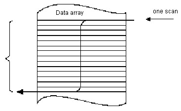
All Mode
In All mode, all the specified elements in the array are operated on before continuing on to the next instruction. The operation begins when the instruction’s EnableIn goes from false to true. The position (.POS) value in the control structure points to the element in the array that the instruction is currently using. Operation stops under two conditions. When the .POS value equals or exceeds the .LEN value, AND when the expression evaluates to true.
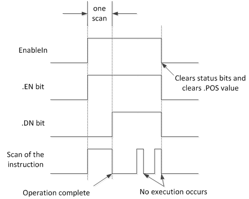
The following timing diagram shows the relationship between status bits and instruction operation. When the instruction execution is complete, the .DN bit is true. The .DN bit, the .EN bit, and the .POS value are cleared when the EnableIn is false. Only then can another execution of the instruction be triggered by a false-to-true transition of EnableIn.
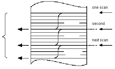
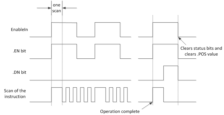
Numerical Mode
Numerical mode distributes the array operation over a number of scans. This mode is useful when working with non-time-critical data or large amounts of data. You enter the number of elements to operate on for each scan, which keeps scan time shorter.
Execution is triggered when the EnableIn goes from false to true. Once triggered, the instruction is executed each time it is scanned for the number of scans necessary to complete operating on the entire array. Once triggered, EnableIn can change repeatedly without interrupting execution of the instruction.
Avoid using the results of a file instruction operating in numerical mode until the .DN or .IN bit is true.
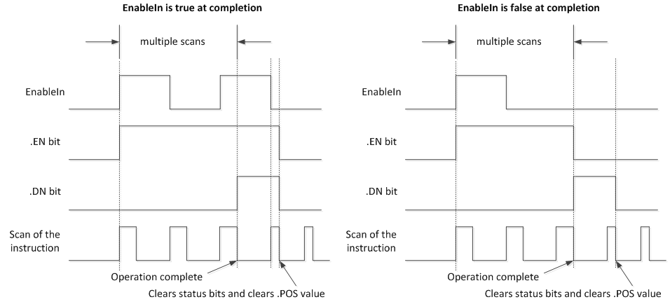
The following timing diagram shows the relationship between status bits and instruction operation. When the instruction execution is complete, the .DN bit is true.
If the EnableIn is true at completion, the .EN and .DN bit are true until the EnableIn goes false. When the EnableIn goes false, these bits are cleared and the .POS value is cleared.
If the EnableIn is false at completion, the .EN bit is cleared immediately. One scan after the .EN bit is cleared, the .DN bit and the .POS value are cleared.
Incremental Mode
Incremental mode manipulates one element of the array each time the instruction’s EnableIn goes from false to true.
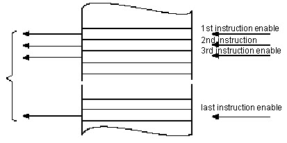
The following timing diagram shows the relationship between status bits and instruction operation. Execution occurs only in a scan in which the EnableIn goes from false to true. Each time this occurs, only one element of the array is manipulated. If the EnableIn remains true for more than one scan, the instruction only executes during the first scan.
The .EN bit is set when rung-condition-in is true. The .DN bit is set when the last element in the array has been manipulated. When the last element has been manipulated and the rung-condition-in goes false, the .EN bit, the .DN bit, and the .POS value are cleared.
The difference between incremental mode and numerical mode at a rate of one element per scan is:
Numerical mode with any number of elements per scan requires only one false-to-true transition of the EnableIn to start execution. The instruction continues to execute the specified number of elements each scan until completion regardless of the state of the EnableIn.
Incremental mode requires the EnableIn to change from false to true to manipulate one element in the array.
Format expressions
For each operator that you use in an expression, you must provide one or two operands (tags or immediate values). Use the following table to format operators and operands within an expression.
For operators that operate on: | Use this format: | Example |
|---|---|---|
One operand | operator(operand) | ABS(tag) |
Two operands | operand_a operator operand_b | tag_b + 5 tag_c AND tag_d (tag_e**2) MOD (tag_f / tag_g) |
Determine the order of operation
The operations you write into the expression are performed by the instruction in a prescribed order, not necessarily the order you write them. You can override the order of operation by grouping terms within parentheses, forcing the instruction to perform an operation within the parentheses ahead of other operations.
Operations of equal order are performed from left to right.
Order | Operation |
|---|---|
1 | ( ) |
2 | ABS, ACS, ASN, ATN, COS, DEG, FRD, LN, LOG, RAD, SIN, SQR, TAN, TOD, TRN |
3 | ** |
4 | - (negate), NOT, ! |
5 | *, /, MOD |
6 | - (subtract), + |
7 | AND |
8 | XOR |
9 | OR |
10 | <, <=, >, >=, =, <> |
11 | && |
12 | ^^ |
13 | || |
Use strings in an expression
To use strings of ASCII characters in an expression, follow these guidelines:
An expression lets you compare two string tags.
You cannot enter ASCII characters directly into the expression.
Only the following operands are permitted:
Operator | Description |
|---|---|
= | Equal |
< | Less than |
<= | Less than or equal |
> | Greater than |
>= | Greater than or equal |
<> | Not equal |
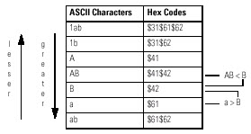
Strings are equal if their characters match.
ASCII characters are case-sensitive. Uppercase A ($41) is not equal to lowercase a ($61).
The hexadecimal values of the characters determine if one string is less than or greater than another string.
When the two strings are sorted as in a telephone directory, the order of the strings determine which one is greater.
Affects Math Status Flags
See Math status flags.
Major/Minor Faults
A major fault will occur if: | Fault type | Fault code |
|---|---|---|
.POS < 0 or .LEN < 0 | 4 | 21 |
See Common Attributes for operand related faults. See Index through arrays for array-indexing faults.
Execution
Ladder Diagram
Condition / State | Action Taken |
|---|---|
Prescan | N/A |
Rung-condition-in is false | See FSC Flow Chart (Rung-condition-out is False) |
Rung-condition-in is true | See FSC Flow Chart (Rung-condition-out is True) |
Postscan | N/A |
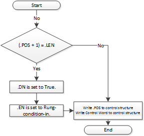
FSC Flow Chart (Rung-condition-out is False)
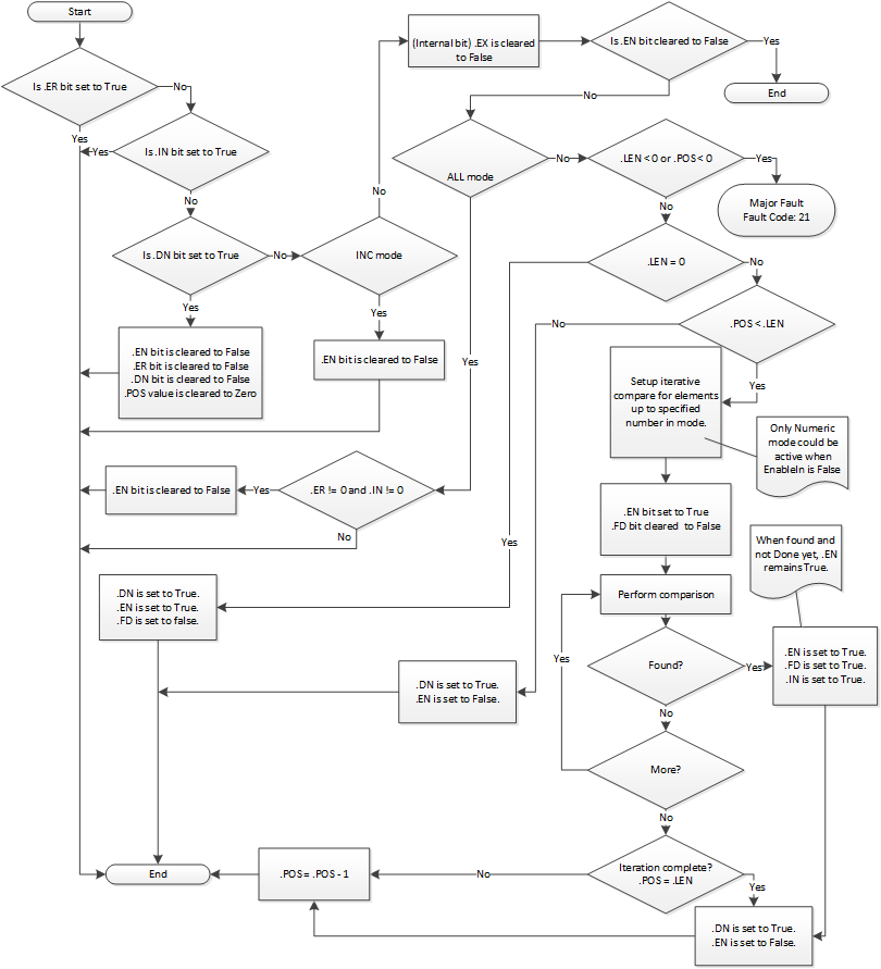
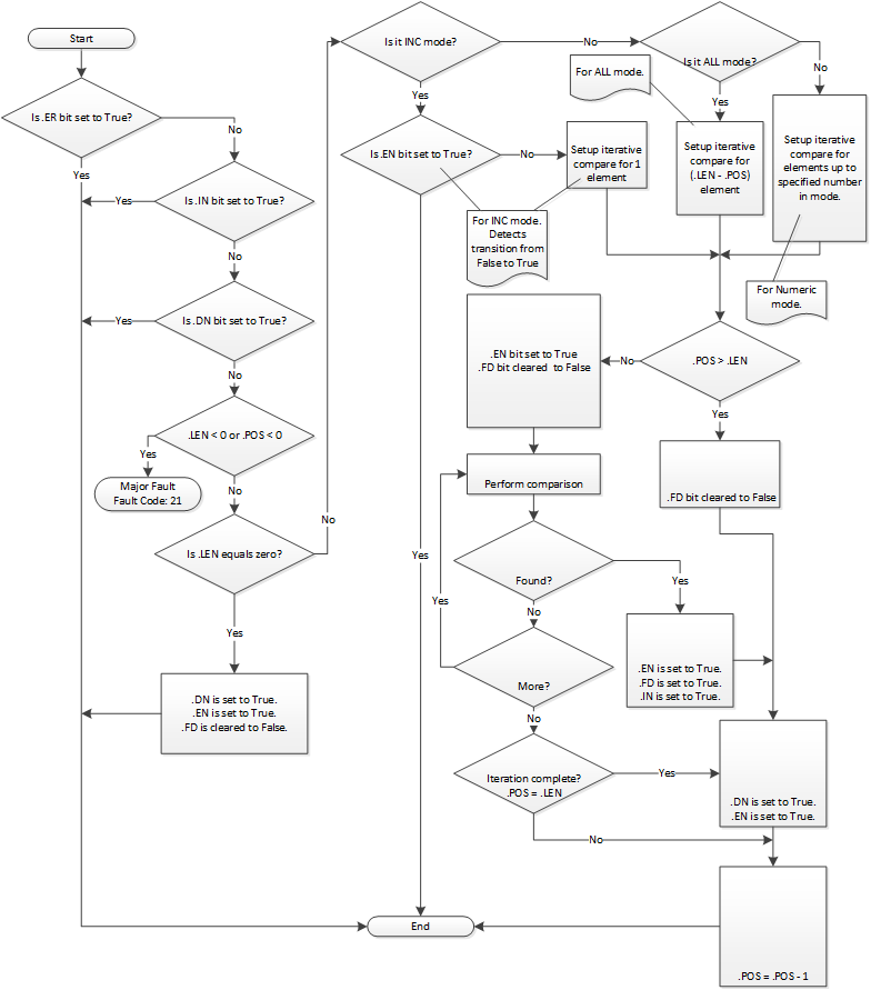
FSC Flow Chart (Rung-condition-out is True)
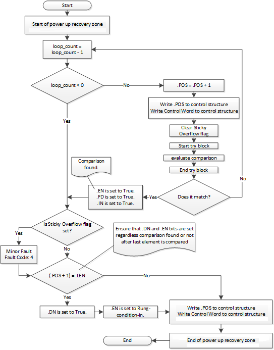
FSC Flow Chart (FSC Common Subflow)
FSC Flow Chart (FSC Common Exception Subflow)
Examples
Example 1
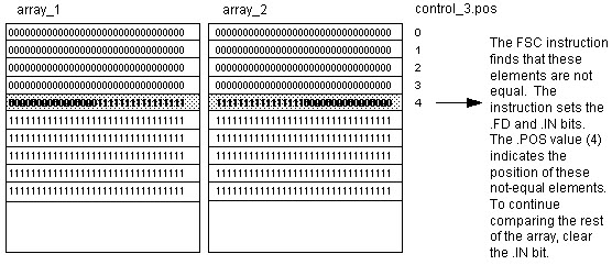
Search between two DINT arrays for elements that are not equal.
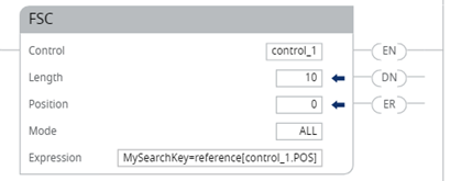
Ladder Diagram
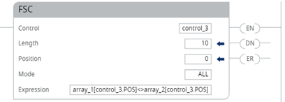
When enabled, the FSC instruction compares each of the first 10 elements in array_1 to the corresponding elements in array_2. When an element is found that is not equal, the FD and IN bits are set. The POS identifies the location of the not equal elements. Clear the IN bit to search the rest of the array.
Example 2
Search for a string within a STRING array.
When enabled, the FSC instruction compares characters in code to 10 elements in code_table.
When a string in code_table is found that matches code, the FD and IN bits are set. The POS identifies the location of the matching strings. Clear the IN bit to search the rest of the array.
Provide Feedback