Diagnostic Detect (DDT)
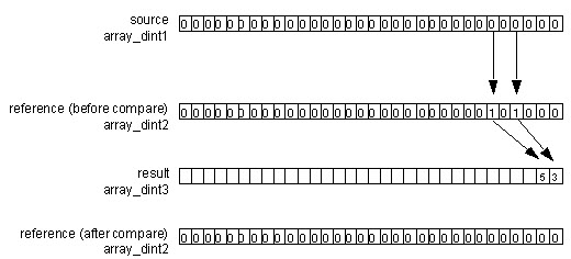
The DDT instruction compares bits in a Source array with bits in a Reference array to find mismatch bit. The mismatch bit location is then recorded and the mismatch Reference bit is changed to match Source bit.
When enabled, the DDT instruction compares the bits in the Source array with the bits in the Reference array, records the bit number of each mismatch in the Result array, and changes the value of the Reference bit to match the value of the corresponding Source bit.
IMPORTANT:
The DDT instruction operates on contiguous memory. You must test and confirm that the instruction does not change data that you don’t want it to change.
The difference between the DDT and FBC instructions is that each time the DDT instruction finds a mismatch, the DDT instruction changes the reference bit to match the source bit. The FBC instruction does not change the reference bit.
If the instruction tries to read past the end of an array, the instruction sets the .ER bit and generates a major fault.
Available Languages
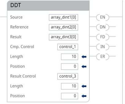
Ladder Diagram
_v1.png/_jcr_content/renditions/original)
Operands
There are data conversion rules for mixed data types within an instruction. See Data Conversion.
Ladder Diagram
Operand | Type | Format | Description |
|---|---|---|---|
Source | DINT | array tag | Array to compare to the reference do not use CONTROL.POS in the subscript |
Reference | DINT | array tag | Array to compare to the source do not use CONTROL.POS in the subscript |
Result | DINT | array tag | Array to store the results do not use CONTROL.POS in the subscript |
Cmp. Control | CONTROL | structure | Control structure for the compare |
Length | DINT | immediate | Number of bits to compare |
Position | DINT | immediate | Current position in the source initial value typically 0 |
Result control | CONTROL | structure | Control structure for the results |
Length | DINT | immediate | Number of storage locations in the result |
Position | DINT | immediate | Current position in the result initial value typically 0 |
IMPORTANT:
Use different tags for the compare control structure and the result control structure. Using the same tag for both could result in unpredictable operation, possibly causing equipment damage and/or injury to personnel.
COMPARE Structure
Mnemonic | Data Type | Description |
|---|---|---|
.EN | BOOL | The enable bit indicates the DDT instruction is enabled. |
.DN | BOOL | The done bit is set when the DDT instruction compares the last bit in the Source and Reference arrays. |
.FD | BOOL | The found bit is set each time the DDT instruction records a mismatch (one-at-a-time operation) or after recording all mismatches (all-per-scan operation). |
.IN | BOOL | The inhibit bit indicates the DDT search mode. 0 = all mode 1 = one mismatch at a time mode |
.ER | BOOL | The error bit is either POS or LEN are invalid. |
.LEN | DINT | The length value identifies the number of bits to compare. |
.POS | DINT | The position value identifies the current bit. |
RESULT Structure
Mnemonic | Data Type | Description |
|---|---|---|
.DN | BOOL | The done bit is set when the Result array is full. |
.LEN | DINT | The length value identifies the number of storage locations in the Result array. |
.POS | DINT | The position value identifies the current position in the Result array. |
Select the search mode
If you want to detect: | Select this mode: |
|---|---|
One mismatch at a time | Set the .IN bit in the compare CONTROL structure. Each time the EnableIn goes from false to true, the DDT instruction searches for the next mismatch between the Source and Reference arrays. Upon finding a mismatch, the instruction stops, sets the .FD bit, and records the position of the mismatch. |
All mismatches | Clear the .IN bit in the compare CONTROL structure. Each time the EnableIn goes from false to true, the DDT instruction searches for all mismatches between the Source and Reference arrays. |
Affects Math Status Flags
No
Major/Minor Faults
A major fault will occur if: | Fault type | Fault code |
|---|---|---|
result.POS > size of result array | 4 | 20 |
See Common Attributes for operand related faults.
Execution
Ladder Diagram
Condition/State | Action Taken |
|---|---|
Prescan | See DDT Flow Chart (Prescan) |
Rung-condition-in is false | See DDT Flow Chart (False) |
Rung-condition-in is true | See DDT Flow Chart (True) |
Postscan | N/A |
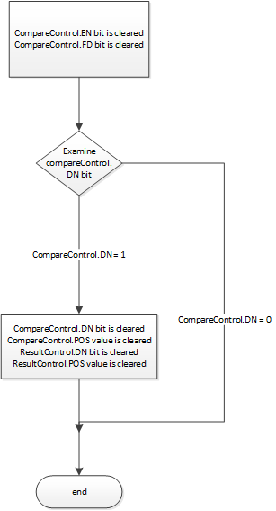
DDT Flow Chart (Prescan)
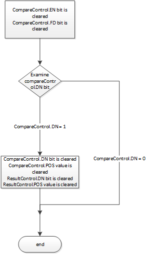
DDT Flow Chart (False)
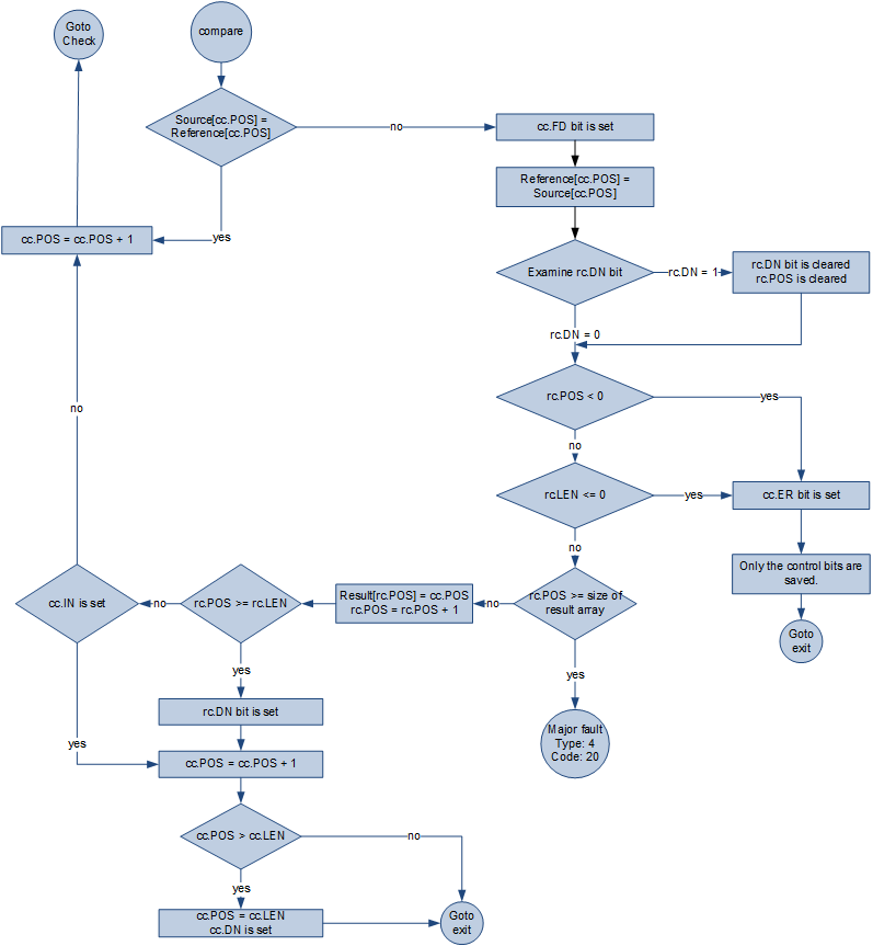
DDT Flow Chart (True)

DDT Flow Chart (True) – Continued
Examples
Ladder Diagram
Provide Feedback