Proportional Integral Derivative (PID)
The PID instruction controls a process variable such as flow, pressure, temperature, or level.
The PID instruction typically receives the process variable (PV) from an analog input module and modulates a control variable output (CV) on an analog output module in order to maintain the process variable at the desired setpoint.
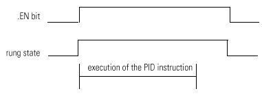
The .EN bit indicates execution status. The .EN bit is set when the EnableIn transitions from false to true. The .EN bit is cleared when the EnableIn becomes false. The PID instruction does not use a .DN bit. The PID instruction executes every scan as long as the EnableIn is true.
Available Languages
Ladder Diagram
_v1.png/_jcr_content/renditions/original)
FactoryTalk Design Studio
DSL - Ladder DiagramPID(PID,ProcessVariable,Tieback,ControlVariable,PIDMasterLoop,InHoldBit,InHoldValue);
Operands
There are data conversion rules for mixed data types within an instruction. See Data Conversion.
Ladder Diagram
Operand | Type | Format | Description |
|---|---|---|---|
PID | PID | structure | PID structure |
Process variable | SINT | tag | Value you want to control |
INT | |||
DINT | |||
REAL | |||
Tieback | SINT | immediate | (optional) |
INT | tag | ||
DINT | Output of a hardware hand/auto station which is bypassing the output of the controller. Enter 0 if you don’t want to use this parameter | ||
REAL | |||
Control variable | SINT | tag | Value which goes to the final control device (valve, damper, etc.) |
INT | |||
DINT | If you are using the deadband, the Control variable must be REAL or it will be forced to 0 when the error is within the deadband. | ||
REAL | |||
PID master loop | PID | Structure | Optional |
PID tag for the master PID | |||
If you are performing cascade control and this PID is a slave loop, enter the name of the master PID | |||
Enter 0 if you do not want to use this parameter | |||
Inhold bit | BOOL | tag | Optional |
Current status of the inhold bit from a 1756 analog | |||
Output channel to support bumpless restart | |||
Inhold value | SINT | tag | Optional |
INT | Data readback value from a 1756 analog output | ||
DINT | Channel to support bumpless restart | ||
REAL | Enter 0 if you don’t want to use this parameter | ||
Setpoint | Display only | ||
Current value of the setpoint | |||
Process variable | Display only | ||
Current value of the scaled Process_Variable | |||
Output % | Display only | ||
Current output percentage value |
PID structure
Specify a unique PID structure for each PID instruction.
Mnemonic | Data Type | Description |
|---|---|---|
.CTL | DINT | The .CTL member provides access to the status members (bits) in one, 32-bit word. Bits 07-15 are set by the PID instruction. See .CTL member. |
.SP | REAL | setpoint |
.KP | REAL | Independent - proportional gain (unitless) |
Dependent - controller gain (unitless) | ||
.KI | REAL | Independent - integral gain (1/sec) |
Dependent - reset time (minutes per repeat) | ||
.KD | REAL | Independent - derivative gain (seconds) |
Dependent - rate time (minutes) | ||
.BIAS | REAL | feedforward or bias % |
.MAXS | REAL | maximum engineering unit scaling value |
.MINS | REAL | minimum engineering unit scaling value |
.DB | REAL | deadband engineering units |
.SO | REAL | set |
.MAXO | REAL | maximum output limit (% of output) |
.MINO | REAL | minimum output limit (% of output) |
.UPD | REAL | loop update time (seconds) |
.PV | REAL | scaled PV value |
.ERR | REAL | scaled error value |
.OUT | REAL | output % |
.PVH | REAL | process variable high alarm limit |
.PVL | REAL | process variable low alarm limit |
.DVP | REAL | positive deviation alarm limit |
.DVN | REAL | negative deviation alarm limit |
.PVDB | REAL | process variable alarm deadband |
.DVDB | REAL | deviation alarm deadband |
.MAXI | REAL | maximum PV value (unscaled input) |
.MINI | REAL | minimum PV value (unscaled input) |
.TIE | REAL | tieback value for manual control |
.MAXCV | REAL | maximum CV value (corresponding to 100%) |
.MINCV | REAL | minimum CV value (corresponding to 0%) |
.MINITIE | REAL | minimum tieback value (corresponding to 100%) |
.MAXTIE | REAL | maximum tieback value (corresponding to 0%) |
.DATA[17] | REAL | The .DATA member stores:
|
The .CTL member
Bit | Number | Description |
.EN | 31 | |
.CT | 30 | cascade type (0=slave; 1=master) |
.CL | 29 | cascade loop (0=no; 1=yes) |
.PVT | 28 | process variable tracking (0=no; 1=yes) |
.DOE | 27 | derivative of (0=PV; 1=error) |
.SWM | 26 | software mode (0=no-auto); 1=yes- sw manual) |
.CA | 25 | control action (0=reverse (SP-PV); 1=direct (PV- SP)) |
.MO | 24 | station mode (0=automatic; 1=manual) |
.PE | 23 | PID equation (0=independent; 1=dependent) |
.NDF | 22 | derivative smoothing (0=no; 1=yes) |
.NOBC | 21 | bias calculation (0=no; 1=yes) |
.NOZC | 20 | zero crossing (0=no; 1=for deadband) |
.INI | 15 | PID initialized (0=no; 1=yes) |
.SPOR | 14 | setpoint out of range (0=no; 1=yes) |
.OLL | 13 | CV is below minimum output value (0=no; 1=yes) |
.OLH | 12 | CV is above maximum output value (0=no; 1=yes) |
.EWD | 11 | error is within deadband (0=no; 1=yes) |
.DVNA | 10 | error is alarmed low (0=no; 1=yes) |
.DVPA | 9 | error is alarmed high (0=no; 1=yes) |
.PVLA | 8 | PV is alarmed low (0=no; 1=yes) |
.PVHA | 7 | PV is alarmed high (0=no; 1=yes) |
Affects Math Status Flags
No
Major/Minor Faults
A minor fault will occur if: | Fault Type | Fault Code |
|---|---|---|
UPD ≥ 0 | 4 | 35 |
setpoint out of range | 4 | 36 |
See Common Attributes for operand-related faults.
Provide Feedback