- Studio 5000 Logix Designer
- Tasks, programs, and routines
- Add-On Instructions
- Controller Organizer
- Logical Organizer
- Alarms
- Tag-based alarms
- Tag Editor and Data Monitor
- Configure settings for Tag Editor and Data Monitor
- Equipment phases
- Equipment Sequences
- Equipment Sequence Diagrams
- Ladder Editor
- Structured Text Editor
- Sequential Function Chart Editor
- Define the steps of an SFC process
- PlantPAx instruction properties
- Controller Properties
- Editing Controller Properties
- Controller Security
- Source Protection
- License Source Protection for Routines and Add-On Instructions
- Module Information
- 1756 ControlLogix I/O Modules
- Instruction Set
S-Curve (SCRV)
This information applies to the
CompactLogix
5370, ControlLogix
5570, Compact GuardLogix
5370, GuardLogix
5570, CompactLogix
5380, CompactLogix
5480, and ControlLogix
5580 controllers.The SCRV instruction performs a ramp function with an added jerk rate. The jerk rate is the maximum rate of change of the rate used to ramp output to input.
Available Languages
Ladder Diagram
This instruction is not available in ladder diagram.
Function Block

Structured Text
SCRV(SCRV_tag);
Operands
Function Block
Operand | Type | Format | Description |
|---|---|---|---|
SCRV tag | S_CURVE | Structure | SCRV structure |
Structured Text
Operand | Type | Format | Description |
|---|---|---|---|
SCRV tag | S_CURVE | Structure | SCRV structure |
See Structured Text Syntax for more information of the syntax of expressions within structured text.
S_CURVE Structure
Input Parameter | Data Type | Description |
|---|---|---|
EnableIn | BOOL | Enable input. If cleared, the instruction does not execute and outputs are not updated.
Default is set. |
In | REAL | The analog signal input to the instruction.
Valid = any float
Default = 0.0 |
Initialize | BOOL | The Initialize input to the instruction. When set, the instruction holds Out = InitialValue
Default is cleared. |
InitialValue | REAL | Initial value of S-Curve. When Initialize is set, Out = InitialValue.
Valid = any float
Default = 0.0 |
AbsAlgRamp | BOOL | Ramp type. If set, the instruction functions as an absolute value ramp. If cleared, the instruction functions as an algebraic ramp.
Default is set |
AccelRate | REAL | Acceleration rate in input units per second2. A value of zero prevents Out form accelerating. When AccelRate < 0, the instruction assumes AccelRate = 0 and sets the appropriate bit in Status. Valid = 0.0 to maximum positive float Default = 0.0 |
DecelRate | REAL | Deceleration rate in input units per second2. A value of zero prevents Out form decelerating. When the DecelRate < 0, the instruction assumes DecelRate = 0 and sets the appropriate bit in Status. Valid = 0.0 to maximum positive float Default = 0.0 |
JerkRate | REAL | Jerk rate in input units per second 3 . Specifies the maximum rate of change in the acceleration and deceleration rates when ramping output to input. When (JerkRate * DeltaT) S AccelRate or DecelRate, the acceleration and deceleration rates are not bounded. In this situation, the instruction behaves as a ramp function. When JerkRate < 0, the instruction assumes JerkRate = 0 and sets the appropriate bit in Status.Valid = 0.0 to maximum positive float Default = 0.0 |
HoldMode | BOOL | S-Curve hold mode parameter. This parameter is used with the HoldEnable parameter. If HoldMode is set when HoldEnable is set and Rate = 0, the instruction holds Out constant. In this situation, the instruction holds Out as soon as HoldEnable is set, the JerkRate is ignored, and Out produces a "corner" in its profile. If HoldMode is cleared when HoldEnable is set, the instruction uses the JerkRate to bring Out to a constant value. Out is held when Rate = 0. Do not change HoldMode once HoldEnable is set because the instruction will ignore the change.
Default is cleared. |
HoldEnable | BOOL | S-Curve hold enable parameter. When set, Out is held. When cleared, Out moves from its current value until it equals In.
Default is cleared. |
TimingMode | DINT | Selects timing execution mode. 0 = periodic mode 1 = oversample mode 2 = real time sampling mode For more information about timing modes, see Function Block Attributes.
Valid = 0 to 2
Default = 0 |
OversampleDT | REAL | Execution time for oversample mode.
Valid = 0 to 4194.303 seconds
Default = 0 |
RTSTime | DINT | Module update period for real time sampling mode
Valid = 1 to 32,767ms
Default = 1 |
RTSTimeStamp | DINT | Module time stamp value for real time sampling mode.
Valid = 0 to 32,767ms
Default = 0 |
Output Parameter | Data Type | Description |
|---|---|---|
EnableOut | BOOL | Enable output. |
S_Mode | BOOL | S_Mode Output. When (Jerk * DeltaT)  Rate and Rate and
Rate < Accel or Decel, S_Mode is set. Otherwise, S_Mode is cleared. |
Out | REAL | The output of the S-Curve instruction. Math status flags are set for this output. |
Rate | REAL | Internal change in the Out in units per second. |
DeltaT | REAL | Elapsed time between updates. This is the elapsed time in seconds used by the control algorithm to calculate the process output. |
Status | DINT | Status of the function block. |
InstructFault (Status.0) | BOOL | The instruction detected one of the following execution errors. This is not a minor or major controller error. Check the remaining status bits to determine what occurred. |
AcceRateInv (Status.1) | BOOL | AccelRate is negative. |
DecelRateInv (Status.2) | BOOL | DecelRate is negative. |
JerkRateInv (Status.3) | BOOL | JerkRate is negative. |
TimingModeInv (Status.27) | BOOL | Invalid timing mode.
For more information about timing modes, see Function Block Attributes. |
RTSMissed (Status.28) | BOOL | Only used in real time sampling mode. Set when
ABS | DeltaT - RTSTime | > 1 (.001 second). |
RTSTimeInv (Status.29) | BOOL | Invalid RTSTime value. |
RTSTimeStampInv (Status.30) | BOOL | Invalid RTSTimeStamp value. |
DeltaT (Status.31) | BOOL | Invalid DeltaT value. |
Description
The primary requirement of the SCRV instruction is to ensure that the rate never changes by more than the specified jerk rate.
You can configure the SCRV instruction to produce an S-Curve profile or a Ramp profile for a step input.
S-Curve Profile
To produce an S-Curve profile, set JerkRate such that (JerkRate * DeltaT) < AccelRate and/or DecelRate.
In S-Curve profile mode, the SCRV instruction ensures that the rate never changes more than the specified JerkRate. The algorithm used to produce the S-Curve profile is designed to produce a smooth, symmetric S-Curve for a step input. A trapezoidal integration of Out is incorporated to facilitate this. As a result, changes in Rate will be less than JerkRate during portions of the profile.
When a step change occurs on the input, rate is increased to the programmed AccelRate or DecelRate. The AccelRate or DecelRate is maintained until a point at which rate must begin decreasing in order for the output to reach input when rate reaches zero.
In some cases, depending on the values of acceleration, deceleration, and jerk, the acceleration rate or deceleration rate might not be reached before the rate must begin decreasing by jerk rate.
For very small step changes, the SCRV instruction will not attempt to produce an 'S' profile. In this mode the entire step will be output and Rate will reflect the change in output. This behavior will occur if Out = In and the next step change to In can be output with a rate less than or equal to the programmed JerkRate.
The SCRV instruction supports an algebraic ramp and an absolute value ramp. For an algebraic ramp, the acceleration condition is defined by an input that is becoming more positive, and the deceleration condition is defined by an input that is becoming more negative. For an absolute value ramp, the acceleration condition is defined by an input moving away from zero, and the deceleration condition is defined by an input moving towards zero.
Ramp Profile
To produce a Ramp profile, set JerkRate such that (JerkRate * DeltaT) AccelRate and/or DecelRate.
AccelRate and/or DecelRate.In Ramp Profile mode, the SCRV instruction always produces a rate of change equal to the programmed AccelRate or DecelRate until the difference between Out and In requires less then AccelRate or DecelRate to reach endpoint.
HoldMode = 0 operates the same as HoldMode = 1. When HoldEnable is set, Out is immediately held and Rate becomes zero.
The following diagram illustrates how the instruction modifies Out.

(1)
When Initialize is set, the instruction sets the following:Outn = InitialValue
Outn-1 = Outn
Raten = 0
Raten-1 = 0
(2)
When HoldMode is cleared, Out is moving toward In, and HoldEnable is set, the rate begins decreasing towards zero at the jerk rate. Due to the JerkRate, Out is held at whatever value it had when the rate reached zero. When the Out is finally held constant, it has a value that is different from the value it had the instant that HoldEnable was set. When HoldMode is set, Out is moving toward In, and HoldEnable is set, the rate is immediately set to zero. Out is held at whatever value it had when HoldEnable was set.
Reducing the JerkRate during a transition might cause Out to overshoot the In. If overshoot occurs, it is the result of enforcing the entered JerkRate. You can avoid an overshoot by decreasing JerkRate in small steps while tuning or by changing JerkRate while Out = In (not during a transition).
The time that is required for Out to equal a change in the input is a function of AccelRate, JerkRate, and the difference between In and Out.
Calculating Output and Rate Values
In transition from an initial value to final value, Out goes through three regions. In region 1 and region 3, the rate of change of Out is based on JerkRate. In region 2, the rate of change of Out is based on AccelRate or DecelRate.

The Out is calculated for each region as follows:

with these equations for each region:
Region | Equation |
|---|---|
region 1 | 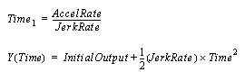 |
region 2 | 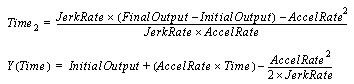 |
region 3 | 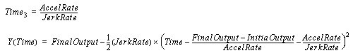 |
When:

the SCRV block does not reach the AccelRate or DecelRate. The Out does the following:

where:

Affects Math Status Flags
No
Major/Minor Faults
None specific to this instruction. See Common Attributes for operand-related faults.
Execution
Function Block
Condition | Function Block Action |
|---|---|
Prescan | EnableIn and EnableOut bits are cleared to false. |
Tag.EnableIn is false | EnableIn and EnableOut bits are cleared to false. |
Tag.EnableIn is true | EnableIn and EnableOut bit bits are set to true The instruction executes. |
Instruction first run | N/A |
Instruction first scan | Clear previous scan data. |
Postscan | EnableIn and EnableOut bits are cleared to false |
Structured Text
Condition/State | Action Taken |
|---|---|
Prescan | See Prescan in the Function Block table. |
Normal Execution | See Tag.EnableIn is true in the Function Block table. |
Postscan | See Postscan in the Function Block table. |
Example
In most coordinated drive applications, a master reference commands line speed for an entire group of drives. As various references are selected, the drives cannot be presented with "step" changes in speed reference because differences in load inertia, motor torque, and tuning would not allow the individual drive sections to react in a coordinated manner. The SCRV instruction is designed to ramp and shape the reference signal to the drive sections so that acceleration, deceleration, and jerk, (derivative of acceleration,) are controlled. This instruction provides a mechanism to allow the reference to the drives to reach the designated reference setpoint in a manner that eliminates excessive forces and excessive impact on connected machinery and equipment.
Function Block

Structured Text
SSUM_01.In1 := Master_reference;
SSUM_01.Select1 := master_select;
SSUM_01.In2 := Jog_reference;
SSUM_01.Select2 := jog_select;
SSUM(SSUM_01);
select_out := SSUM_01.Out;
SCRV_01.In := select_out;
SCRV_01.AccelRate := accel;
SCRV_01.DecelRate := accel;
SCRV_01.JerkRate := jerk_rate;
SCRV(SCRV_01);
scurve_out := SCRV_01.Out
Provide Feedback