Motion Axis Move (MAM)
CompactLogix
5380, CompactLogix
5480, ControlLogix
5580, Compact GuardLogix
5380, and GuardLogix
5580 controllersUse the Motion Axis Move (MAM) instruction to move an axis to a specified position.
This is a transitional instruction. Follow these steps when using it:
- In ladder logic, insert an instruction to toggle the rung-condition-in from false to true each time the instruction should execute.
- In a Structured Text routine, insert a condition for the instruction to cause it to execute only on a transition.
Architecture | Standard | Safety |
|---|---|---|
CompactLogix 5370, ControlLogix 5570, Compact GuardLogix 5370, and GuardLogix 5570 controllers | Yes | No |
Compact GuardLogix 5380, CompactLogix 5380, CompactLogix 5480, ControlLogix 5580, and GuardLogix 5580 controllers | Yes | No |
Available Languages
Ladder Diagram

Function Block
This instruction is not available in function block.
Structured Text
MAM(Axis, MotionControl, MoveType, Position, Speed, SpeedUnits, AccelRate, AccelUnits, DecelRate, DecelUnits, Profile, AccelJerk, DecelJerk, JerkUnits, Merge, MergeSpeed, LockPosition, LockDirection, EventDistance, CalculatedData);
Operands
Ladder Diagram
Operand | Type Tip: AXIS_CONSUMED is supported by Compact GuardLogix 5580, CompactLogix 5380, and CompactLogix 5480 controllers only. | Type Tip: AXIS_GENERIC is supported by the ControlLogix 5570 and the GuardLogix 5570 controllers only. | Format | Description | ||
|---|---|---|---|---|---|---|
Axis | AXIS_CIP_DRIVE AXIS_VIRTUAL | AXIS_CIP_DRIVE AXIS_VIRTUAL AXIS_GENERIC_DRIVE AXIS_SERVO AXIS_SERVO_DRIVE | Tag | Name of the axis. For an Absolute or Incremental Master Offset move, enter the slave axis. For controllers that support the REF_TO motion data types, the supported axis operand type can be replaced by an equivalent REF_TO type. | ||
Motion Control | MOTION_
INSTRUCTION | MOTION_
INSTRUCTION | Tag | Control tag for the instruction | ||
Move type | DINT | DINT | Immediate or Tag | To | Use This Move Type | And Enter |
Move an axis to an absolute position | Absolute | 0 | ||||
Move an axis a specified distance from where it is now | Incremental | 1 | ||||
Move a Rotary axis to an absolute position in the shortest | Rotary Shortest Path | 2 | ||||
Move a Rotary axis to an absolute position in the positive direction regardless of its current position | Rotary Positive | 3 | ||||
Move a Rotary axis to an absolute position in the negative direction regardless of its current position | Rotary Negative | 4 | ||||
Offset the master value of a position cam to an absolute position | Absolute Master Offset | 5 | ||||
Offset the master value of a position cam by an incremental distance | Incremental Master Offset | 6 | ||||
See Choose a Move Type for a Rotary Axis below for more information about rotary moves. | ||||||
Position | REAL | REAL | Immediate or Tag | Absolute position or incremental distance for the move | ||
For This Move Type | Enter This Position Value | |||||
Absolute | Position to Move to | |||||
Incremental | Distance to Move | |||||
Rotary Shortest Path | Position to move to. Enter a positive value that is less than the Position Unwind value. | |||||
Rotary Positive | ||||||
Rotary Negative | ||||||
Absolute Master Offset | Absolute Offset Position | |||||
Incremental Master Offset | Incremental Offset Distance | |||||
Speed | REAL | REAL | Immediate or Tag | Speed to move the axis in Speed Units | ||
Speed Units | DINT | DINT | Immediate | Which units do you want to use for the Speed? Units per sec (0) % of Maximum (1) Time (3) Units per MasterUnit (4) Master Units (7) | ||
Accel Rate | REAL | REAL | Immediate or Tag | Acceleration rate of the axis in Accel Units | ||
Accel Units | DINT | DINT | Immediate | Which units do you want to use for the Accel Rate? Units per sec 2 (0)% of Maximum (1) Time (3) Units per MasterUnit 2 (4)Master Units (7) | ||
Decel Rate | REAL | REAL | Immediate or Tag | Deceleration rate of the axis in Deceleration Units. | ||
Decel Units | DINT | DINT | Immediate | Which units do you want to use for the Decel Rate? Units per sec 2 (0)% of Maximum (1) Time (3) Units per MasterUnit 2 (4)Master Units (7) | ||
Profile | DINT | DINT | Immediate | Select the velocity profile to run for the move:
| ||
Accel Jerk | REAL | REAL | Immediate or Tag | The instruction only uses the jerk operands if the Profile is S-curve. You must always fill them in however.
Use these values to get started.
You can also enter the jerk rates in these Jerk Units.
| ||
Decel Jerk | REAL | REAL | Immediate or Tag | |||
Jerk Units | DINT | DINT | Immediate | |||
Merge | DINT | DINT | Immediate | Do you want to turn all current axis motion into a pure move governed by this instruction regardless of the motion instructions currently in process?
| ||
Merge Speed | DINT | DINT | Immediate | If Merge is Enabled, which speed do you want to move at?
| ||
Lock Position | REAL | REAL | Immediate or Tag | Position on the Master Axis where a Slave should start following the master after the move has been initiated on the Slave Axis. See the Structure section below for more information. | ||
Lock Direction | SINT, INT or DINT | SINT, INT or DINT | Immediate | Specifies the conditions when the Lock Position should be used. Valid Values = 0-4 Default = None (Enumeration 1-4 are currently not allowed in Time Driven or Time Based modes.) See the Structure section below for more information. | ||
Event Distance | REAL ARRAY or 0 | REAL ARRAY or 0 | Array Tag | The position(s) on a move measured from the end of the move. See the Structure section below for more information. | ||
Calculated Data | REAL ARRAY or 0 | REAL ARRAY 0 | Array Tag | Master Distance(s) (or time) needed from the beginning of the move to the Event Distance point. See the Structure section below for more information. | ||
Structured Text
This Operand | Has These Options Which You | |
|---|---|---|
Enter as Text | Or Enter as a Number | |
SpeedUnits | unitspersec %ofmaximum time unitspermasterunit masterunits | 0 1 3 4 7 |
AccelUnits | unitspersec 2 %ofmaximum time
unitspermasterunit 2 masterunits | 0 1 3 4 7 |
DecelUnits | unitspersec 2 %ofmaximum time
unitspermasterunit 2 masterunits | 0 1 3 4 7 |
Profile | trapezoidal scurve | 0 1 |
JerkUnits | unitspersec 3 %ofmaximum %oftime time
unitspermasterunit 3 %oftime-masterdriven masterunits | 0 1 2 3 4 6 7 |
Merge | disabled enabled | 0 1 |
MergeSpeed | programmed current | 0 1 |
Lock Position | No enumeration | Immediate, Real, or Tag |
Lock Direction | None immediateforwardonly immediatereverseonly positionforward positionreverse | 0 1 2 3 4 |
Event Distance | No enumeration | Array or 0 |
Calculated Data | No enumeration | Array or 0 |
See Structured Text Syntax for more information on the syntax of expressions within structured text.
MOTION_INSTRUCTION Data Type
To See If | Check If This Bit Is Set To | Data Type | Notes |
|---|---|---|---|
A false-to-true transition caused the instruction to execute | EN | BOOL | The EN bit stays set until the process is complete and the rung goes false. |
The move was successfully initiated | DN | BOOL | |
An error happened | ER | BOOL | |
The axis is moving to the end Position | IP | BOOL | Any of these actions stop this move and clear the IP bit:
|
The axis is at the end Position | PC | BOOL |
|
Description
The MAM instruction moves an axis to either a specified absolute position or by a specified incremental distance. The MAM instruction can also produce other special types of moves.
Trapezoidal Move Starting from Standstill

Programming Guidelines
WARNING:
Risk of Velocity and/or End Position Overshoot
If you change move parameters dynamically by any method, that is by changing move dynamics [Motion Change Dynamics (MCD)] instruction or by starting a new instruction before the last one has completed, be aware of the risk of velocity and/or end position overshoot.
A Trapezoidal velocity profile can overshoot if maximum deceleration is decreased while the move is decelerating or is close to the deceleration point.
An S-curve velocity profile can overshoot if:
- maximum deceleration is decreased while the move is decelerating or close to the deceleration point; or
- maximum acceleration jerk is decreased and the axis is accelerating. Keep in mind, however, that jerk can be changed indirectly if it is specified in % of time.
For more information, see Troubleshoot Axis Motion
Guideline | Details | |||
|---|---|---|---|---|
In ladder diagram, toggle the rung condition each time you want to execute the instruction. | This is a transitional instruction. In ladder diagram, toggle the rung-condition-in from cleared to set each time you want to execute the instruction. | |||
In structured text, condition the instruction so that it only executes on a transition | In structured text, instructions execute each time they are scanned. Condition the instruction so that it only executes on a transition. Use either of these methods:
For more information, see Structured Text Syntax. | |||
For a Master Offset move, enter the slave axis but use master units. | Use an Absolute or Incremental Master Offset move to off set the master value of a position cam without actually changing the position of the master axis. This shifts the position cam profile along the master axis.
The instruction adds in the offset at the Speed, Acceleration, Deceleration, and Jerk values. | |||
Use % of Time for the easiest programming and tuning of jerk | For an easy way to program and tune jerk, enter it as a % of the acceleration or deceleration time. For more information, see Tune an S-Curve Profile. | |||
Use Merge to cancel the motion of other instructions | How you want to handle any motion that’s already in process? | |||
If you want to | And you want to | Then set | ||
Add the move to any motion already in process |  | Merge = Disabled Merge Speed = Programmed The instruction ignores Merge Speed but you must fill it in anyway. | ||
End the motion from other instructions and just jog | Move at the Speed that you set in this instruction | Merge = Enabled Merge Speed = Programmed | ||
Move at the speed that the axis is already moving | Merge = Enabled Merge Speed = Current The instruction ignores the value that you put in the Speed operand. | |||
Is This an Absolute or Incremental Master Offset Move? If this is an Absolute or Incremental Master Offset move and Merge is Enabled, then the following is true.
| ||||
Use a second MAM instruction to change one that is already in process. | You can change the position, speed, acceleration, or deceleration. The change immediately takes effect. | |||
To Change the Position of An | Set Up a Second MAM Instruction Like This | |||
Absolute Move | Either:
In either case, the axis moves to the new position without stopping at the old position—including any required change of direction. | |||
Incremental Move | Either:
| |||
Combine a move with gearing for complex profiles and synchronization. | You can use a Motion Axis Gear (MAG) instruction together with an MAM instruction. This superimposes the gearing on top of the move or the move on top of the gearing. Example: Superimpose an incremental move on top of electronic gearing for phase advance and retard control. | |||
Choose a Move Type for a Rotary Axis
Move Type | Example | Description |
|---|---|---|
Absolute | Absolute move to 225°. The direction depends on the starting position of the axis. 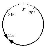 | With an Absolute move, the direction of travel depends on the current position of the axis and is not necessarily the shortest path to the end position. Starting positions less than the end position result in motion in the positive direction, while starting positions greater than the end position result in motion in the negative direction. The specified position is interpreted trigonometrically and can be positive or negative. It can also be greater than the Position Unwind value. Negative position values are equivalent to their corresponding positive values and are useful when rotating the axis through 0. For example, –90° is the same as +270°. When the position is greater than or equal to the Position Unwind value, the axis moves through more than one revolution before stopping at an absolute position. |
Incremental | The specified distance is interpreted trigonometrically and can be positive or negative. It can also be greater than the Position Unwind value. When the distance is greater than the Position Unwind value, the axis moves through more than one revolution before stopping. | |
Rotary Shortest Path | Rotary Shortest Path move from 30° to 225°. 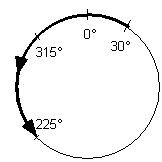 | Important: Only use a Rotary Shortest Path move if the Positioning Mode of the axis is Rotary (Rotary axis).A Rotary Shortest Path move is a special type of absolute move for a Rotary axes. The axis moves:
With a Rotary Shortest Path move, you:
|
Rotary Positive | Rotary Positive move from 315° to 225°. 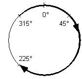 | Important: Only use a Rotary Positive move while the axis is standing still and not moving. Otherwise the axis could move in the wrong direction.A Rotary Positive move is a special type of absolute move for a Rotary axis.
The axis:
You can’t move the axis more than one revolution with a single Rotary Shortest Path move. |
Rotary Negative | Rotary Negative move from 45° to 225°. 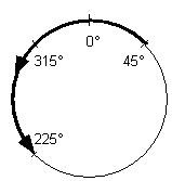 | Important: Only use a Rotary Shortest Path move if
A Rotary Negative move is a special type of absolute move for a Rotary axis. The axis:
You cannot move the axis more than one revolution with a single Rotary Shortest Path move. |
When MAM (Merge = Enabled) is used on any axis associated with a coordinate system and a coordinated motion instruction is running on it, Coordinate system’s maximum deceleration is used to stop remaining axes. If the coordinate system contains orientation axes, Coordinate system’s Orientation maximum deceleration is used for stopping remaining Rx, Ry or Rz axes.
Structure
See Input and Output Parameters Structure for Single Axis Motion Instructions for the input and output parameters that are available for the MAM instruction via the Master Driven Speed Control (MDSC) function. Before any of these parameters is active, you must execute an MDAC instruction and it must be active (IP bit is set).
Affected Math Status Flags
No
Major/Minor Faults
None specific to this instruction. A major fault can occur if an uninitialized reference or a reference of incorrect type is passed to the Axis Operand. See Common Attributes for operand-related faults.
Ladder Diagram
Condition/State | Action Taken |
|---|---|
Prescan | The .EN, .DN, .ER, and .IP bits are cleared to false. |
Rung-condition-in is false | The .EN bit is cleared to false if the .DN or .ER bit is true. |
Rung-condition-out is true | The .EN bit is set to true and the instruction executes. |
Postscan | N/A |
Structured Text
Condition/State | Action Taken |
|---|---|
Prescan | See Prescan in the Ladder Diagram table |
Normal execution | See Rung-condition-in is false, followed by rung is true in the Ladder Diagram table. |
Postscan | See Postscan in the Ladder Diagram table. |
Error Codes
See Error Codes (.ERR) for Motion Instructions.
Runtime Error Condition
The slave move must start at rest if Speed Units = Seconds or Master Units. This condition may occur when the MAM with Speed = Seconds or Master Units is started while another MAM is in progress (merging or replacement mode).
Extended Error Codes
Use Extended Error Codes (EXERR) for more instruction about an error. See Error Codes (.ERR) for Motion Instructions.
If ERR is | And EXERR is | Then | |||
|---|---|---|---|---|---|
Cause | Corrective Action | ||||
13 | Varies | An operand is outside its range. | The EXERR is the number of the operand that is out of range. The first operand is 0. For example, if EXERR = 4, then check the Speed. | ||
EXERR | Operand | ||||
0 | Axis | ||||
1 | Motion Control | ||||
2 | Move Type | ||||
3 | Position | ||||
4 | Speed | ||||
6 | Accel Rate | ||||
8 | Decel Rate | ||||
15 | -1 | The coordinate system has a Maximum Deceleration of 0. | Go to the Properties for the coordinate system axis and set a Maximum Deceleration. | ||
0 or more | An axis in the coordinate system has a Maximum Deceleration of 0. |
| |||
Changes to Status Bits
Motion Instruction Predefined Data Type Status Bits
See Status Bits for Motion Instructions (MAM, MATC, MAJ) When MDAC Is Active.
MAM Changes to Single Axis Status Bits
Bit Name | Meaning | |
|---|---|---|
MotionStatus | The motion status bit for your axis. | |
Bit Number | Meaning | |
AccelStatus | 0 | The axis is not accelerating (FALSE state). |
DecelStatus | 1 | The axis is not decelerating (FALSE state). |
MoveStatus | 2 | The axis is not moving (FALSE state). |
JogStatus | 3 | The axis is not jogging (FALSE state). |
GearingStatus | 4 | The axis is not gearing (FALSE state). |
HomingStatus | 5 | The axis is not homing (FALSE state). |
StoppingStatus | 6 | The axis is stopping (TRUE state). |
AxisHomedStatus | 7 | The axis is not homed (FALSE state). |
PositionCamStatus | 8 | The axis is not position camming (FALSE state). |
TimeCamStatus | 9 | The axis is not time camming (FALSE state). |
PositionCamPendingStatus | 10 | The axis does not have a Position Cam Pending (FALSE state). |
TimeCamPendingStatus | 11 | The axis does not have a Time Cam Pending (FALSE state). |
GearingLockStatus | 12 | The axis is not in a Gear Locked condition (FALSE state). |
PositionCamLockStatus | 13 | The axis is not in a Position Cam Locked condition (FALSE state). |
TimeCamLockStatus | 14 | The axis is not in a Time Cam Locked condition (FALSE state). |
MasterOffsetMoveStatus | 15 | The axis is offset (TRUE state). |
CoordinatedMotionStatus | 16 | Sets when the MDAC instruction executes (TRUE state). Clears when the instruction completes (FALSE state). |
TransformStateStatus | 17 | The axis is part of an active transform (TRUE state). |
ControlledByTransformStatus | 18 | The axis is moving because of a transform (TRUE state). |
DirectVelocityControlStatus | 19 | The axis is not under Direct Velocity Control (FALSE state). |
DirectTorqueControlStatus | 20 | The axis is not under Direct Torque Control (FALSE state). |
MoveLockStatus | 22 | MAM is Locked to Master in MDSC Mode (TRUE state). The bit is cleared when a MGS, MGSD, MAS, or MASD is executed (goes IP). If either the Slave or Master axis (or both) is paused by changing its speed to 0, then the MoveLockStatus bit stays set. Master Driven Mode The bit is set when the Lock Direction request is satisfied. The bit is not used when the enumeration is NONE. For the enumerations Immediate Forward Only and Immediate Reverse Only, the MamLockStatus bit is set immediately when the MAM is initiated. For the enumeration Position Forward Only and Position Reverse Only, the bit is set when the Master Axis crosses the Master Lock Position in the specified direction. The MoveLockStatus bit is cleared when the Master Axis reverses direction and the Slave Axis stops following the Master Axis. The MoveLockStatus bit is set again when the Slave Axis resumes following the Master Axis. Time Driven Mode The bit is not used when the enumeration is NONE. |
JogLockStatus | 24 | The axis is not in a Jog Locked condition (FALSE state). |
MasterOffsetMoveLockStatus | 26 | Master offset Move is Locked to master in MDSC Mode (TRUE state). |
MaximumSpeedExceeded | 27 | Sets when the maximum axis speed that is specified in the axis configuration is exceeded during a move (TRUE state). Clears when the speed is reduced below the limit (FALSE state). |
Motion Status Bits
If the Move Type Is | And Merge is | Then the Instruction Changes These Bits | ||
|---|---|---|---|---|
Bit Name | State | Meaning | ||
NOT Absolute Master Offset or Incremental Master Offset | Disabled | MoveStatus | TRUE | Axis is Moving. |
Enabled | MoveStatus | TRUE | Axis is Moving. | |
JogStatus | FALSE | Axis is no longer Jogging. | ||
GearingStatus | FALSE | Axis is no longer Gearing. | ||
Absolute Master Offset or Incremental Master Offset | | MasterOffsetMoveStatus | TRUE | Axis is Offset. |
Merging in Incremental Mode
The Merge for MAM operates differently from a merge on a Motion Coordinated Linear Move (MCLM) instruction. For the MAM, any uncompleted motion at the point of the merge remains in the move. For example, assume that you have a single axis MAM programmed in incremental mode from a starting absolute position = 0 and with the programmed incremental distance = 4 units. If a merge occurs at an absolute position of 1 and the merge is another incremental move of 4 units, the move completes at a position = 8.
If this example occurs on a Motion Coordinated Linear Move (MCLM) instruction programmed in incremental mode, the final position = 5.
Master Driven Speed Control (MDSC) Merging and Replacement Mode for MAM
When programmed in units of seconds, the MAM instruction must start at rest (that is, both start velocity and acceleration must be equal to 0.0). If programmed in units of seconds or Master Units, a runtime error will occur for the MAM on the Slave if the instruction is activated when not at rest.
Master Driven Speed Control (MDSC) and Motion Direct Command Support
The Motion Direct commands are not available in the instruction tree for the MDAC instruction. You must program an MDAC in one of the supported programming languages before you execute an MAM in Time Driven Mode. A runtime error will occur if an MDAC is not previously executed in an MAM or MAJ in Master Driven Mode.
The Motion Direct Command supports the MDSC enumerations speed, acceleration, deceleration, and Jerk for MAM.
Note that Event Distance and Calculated Data are not supported parameters for the MAM and Motion Direct Command.
Master Driven Speed Control (MDSC) and CIP Axis Manual Tune and Motion Generator
Event Distance and Calculated Data parameters are not supported for MAM.
Provide Feedback